Sawtooth Waveform in Beam Scanning:
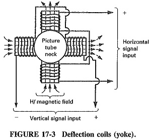
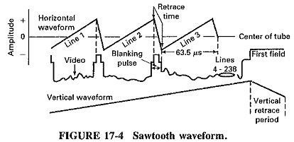
As previously discussed, one complete frame of a TV picture is scanned 30 times per second, in a manner very similar to reading this page. As our eyes are told where to look by our brain, eye muscles, and nerves, the electron beam is directed to move by deflection coils (yoke), which are located around the neck of the picture tube (Figure 17-3). The information applied to the deflection coils is in the form of a Sawtooth Waveform in Beam Scanning (Figure 17-4), generated by the horizontal oscillator, which occurs at a rate or frequency determined by the number of lines (525) to be scanned and the scanning rate (30 frames per second).
The electron beam generated by the picture tube (standard vacuum tube theory) is accelerated toward the anode by a combination of elements and extreme high voltage (difference of potential) until it strikes the anode (which contains a phosphorous coating). The high-energy impact emits light or a dot in the center of the picture tube which is visible to our eyes, The dot would never move without some type of deflection process. This is where the deflection coils and the sawtooth waveforms come into play.
Horizontal Scanning:
The Sawtooth Waveform in Beam Scanning applied to the horizontal portion of the deflection coils (there are two sets of coils – horizontal and vertical) creates a magnetic field which mimics the shape of the sawtooth and deflects the beam to the extreme left side of the picture tube at the start of each cycle. The Sawtooth Waveform in Beam Scanning moves evenly across the tube face as the wave increases in amplitude (because of the linear ramp effect) until maximum amplitude is reached and the voltage drops immediately to its original starting point (retrace period). Up to this point we have traced (illuminated) one line from left to right across the picture tube face. Now the process starts over again on the next cycle. It must be noted that during the horizontal scanning process, vertical scanning is also taking place with similar results; i.e., the vertical deflection coils are being fed information which creates magnetic deflection from the center dot point to the top of the tube. The combination and synchronisation of these two processes start the scanning process at the top left and, line by line, complete the frame at the lower right of the picture tube. The scanning process is, in the author’s opinion, the most important part of the TV system and is unique in its application. The rest of the TV system is composed of somewhat standard electronic circuits which have been assembled to support the scanning process and visually displayed information. This explanation is over simplified to enhance students basic understanding of the process, not to confuse them with details and the electronics involved. A more detailed explanation will follow.
Vertical Scanning:
Vertical scanning is similar to horizontal scanning, except for the obvious difference in the direction of movement and the fact that everything happens much more slowly, (i.e., 60 rather than 15,750 times per second). However, interlacing introduces a complication which will now be explored.
The sequence of events in vertical scanning is as follows:
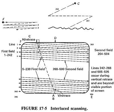
- Line 1 starts at the top left-hand corner of the picture, at point F. At this line and the succeeding lines are scanned horizontally, the Sawtooth Waveform in Beam Scanning gradually moves downward. This continues until, midway through line 242, vertical blanking is applied. The situation is illustrated in Figure 17-5. Note that active horizontal lines are solid, the horizontal retraces are dashed, and the point at which vertical blanking is applied is labeled A.
- Soon, but not immediately, after the application of vertical blanking, the vertical scanning generator receives a (vertical) sync pulse. This causes vertical retrace to commence, at point B in Figure 17-5.
- Vertical retrace continues, for a time corresponding to several H, until the beam reaches the top of the picture, point C in Figure 17-5. Note that horizontal scanning continued during the vertical retrace it would be harmful to.stop the horizontal oscillator just because vertical retrace is taking place.
- The Sawtooth Waveform in Beam Scanning, still blanked out, begins its descent. The precise point is determined by the time constants in the vertical scanning oscillator, but it is usually 5 or 6H between points B and C. The situation is shown in Figure 17-5.
- Precisely 21H after it was applied, i.e., midway through line 263, vertical blanking is removed. The first (odd) field is now completed, and the second (even) field This is also illustrated in Figure 17-5; note that D is the point at which vertical blanking is removed.
- The visible portion of line 263 begins at the same height as did line 1, i.e., at the top of the screen. Line 263, when it becomes visible, is already halfway across the screen, whereas line 1 began at the left-hand edge of the screen. Line 263 lies above line 1, line 264 is between lines 1 and 2, and so on. This is illustrated in Figure 17-5.
- The second field continues, until vertical blanking is applied at the beginning of the retrace after line 504. This is point E in Figure 17-5.
- The sequence of events which now takes place is identical to that already described, for the end of the first field. The only difference is that, after the 21 lines of vertical blanking, the beam is located at the top left-hand corner of the picture tube, at point F. When vertical blanking is now removed, the next odd field is traced out, as in Figure 17-5.
Regrettably, the vertical scanning procedure is complicated by the use of interlacing. However, it is basically simple, in that blanking is applied some time before retrace begins and removed some time after it has ended. Both margins are used for safety and to give individual designers of receivers some flexibility. As explained, horizontal scanning continues during vertical retrace, complicating the drawings and the explanation, but actually simplifying the procedure. To stop the horizontal oscillator for precisely 21 lines, and then to restart it exactly in sync, would simply not be practical: Finally, beginning one field at the start of a line and the next field at the midpoint of a line is a stratagem that ensures that interlacing will take place. If this were not done, the lines of the second field would coincide with those of the first, and vertical resolution would immediately be halved!