Video Test Pattern Generator:
A pattern generator provides video signals directly, and with RF modulation, on standard TV channels for alignment, testing and servicing of TV receivers. The output signal is designed to produce simple geometric patterns like vertical and horizontal bars, checkerboard, cross-hatch, dots, etc. These video test pattern generator are used for linearity and video amplifier adjustment. In addition to this, an FM sound signal is also provided in pattern generators for aligning sound sections of the receiver.
A simplified functional block diagram of a pattern cum sound signal generator is shown in Fig. 8.14.
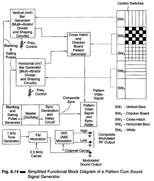
The generator employs two stable chains of multivibrators, dividers and pulse shaping circuits, one below the line frequency to produce a series of horizontal bars, and another above 15625 Hz to produce vertical bars. The signals are modified into short duration pulses, which when fed to the video section of the receiver along with the sync pulse train, produce fine lines on the screen.
Multivibrators produce a square wave video signal at m times the horizontal frequency to provide m vertical black and white bars. After every m cycles, the horizontal blanking pulse triggers the multivibrators for synchronising the bar signal on every line. A control on the front panel of the Video Pattern Generator enables variation of multivibrators frequency to change the number of bars.
Similarly, square wave pulses derived either from 50 Hz mains of from the master oscillator are used to trigger another set of multivibrator to generate square wave video signals that are n times the vertical frequency. On feeding the video amplifier these produce horizontal black and white bars. The number of horizontal bars can also be varied by a potentiometer that controls the switching rate of the corresponding multivibrator. (The bar pattern signal is combined with the sync and blanking pulses in the video adder to produce composite video signals before being fed to the modulator).
The provision of switches in the signal path of the two multivibrators enables the generation of various patterns. If both mH and nV switches are off, a blank white raster is produced. With only the mH switch on, vertical bars are produced, and with only the nV switch on, horizontal bars are generated. With both switches on, a cross-hatch pattern will be produced (Fig. 8.14).
The horizontal bar pattern is used for checking vertical linearity. These bars should be equally spaced throughout the screen for linearity. Similarly, the vertical bar pattern can be used for checking and setting horizontal linearity. With the cross-hatch pattern formed by the vertical and horizontal lines, linearity can be adjusted more precisely, because any unequal spacing of the lines can be discerned.
Picture centering and aspect ratio can also be checked with the cross-hatch pattern by counting the number of squares on the vertical and horizontal sides of the screen.
The Video Test Pattern Generator can also be used for detecting any spurious oscillations in the sweep generation circuits, interaction between the two oscillators, poor interlacing, and barrel and pin cushion effects.
Modulated picture signals are available on limited channels for injecting into the RF section of the receiver.
Similarly, an FM sound signal with a carrier frequency of 5.5 MHz ± 100 kHz, modulated by a 1 kHz tone, is provided for aligning sound IF and discriminator circuits. A 75/300 Ω VHF balun is usually available as a standard accessory with the video test pattern generator.