Series DC Voltage Regulator:
The output voltage of a d.c. source, whether it is a rectifier or any other machine, changes with the load current as well as with the input voltage variations. In order to maintain a constant voltage at the load terminals, it is essential to have a Series DC Voltage Regulator circuit which corrects the variation in voltage. It is essential to keep the change in voltage between ± 0.1% to ± 0.001% depending on the applications.
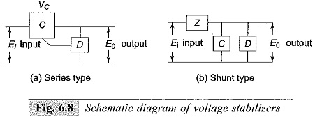
A d.c. voltage regulator consists of detecting elements which sense the change in voltage from the desired value and controlling elements actuated by the detector in such a manner as to correct the changes. Series DC Voltage Regulator are generally of two types
(a) Series type, and
(b) Shunt or Parallel type.
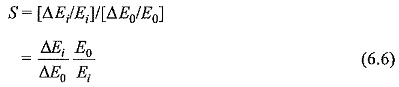
If ΔE0 is the change in E0 as a result of a change of AEi in Ei then the stabilization ratio S is defined as
A second parameter R0 is introduced to define completely the functional performance of a regulator. R0 is the effective internal resistance of the regulator as seen from the output terminals.
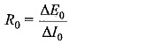
where ΔE0 is the change in the output voltage caused due to a change in load current of ΔI0, with the input voltage remaining constant.
The regulation R is defined as,
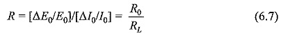
where RL is the load resistance.
Typical series type regulator and degenerative feedback system of voltage regulation are shown in Figs 6.9a and b respectively.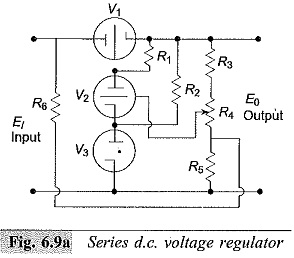
Figure 6.9a shows the simplified diagram of a series type of voltage regulator. Here the gas tube V3 provides the reference voltage which keeps the potential of the cathode of the tube V2 constant. When the output voltage E0 changes, the current through the divider R2,R4 and R5 changes, and hence the bias voltage of the tube V2 with respect to its cathode changes in the opposite manner (reduces when the output voltage increases and vice versa). Thus, the grid potential of V1 is altered in such a manner as to oppose the variation in output voltage E0; that is, the voltage drop across the tube V1 reduces, if the output voltage decreases and vice versa.
Resistance R6 together with R5 provides a voltage input to the d.c. amplifier (the detector) in proportion to fluctuations in the input voltage in such a way as to reduce the effect of these variations in the output voltage.
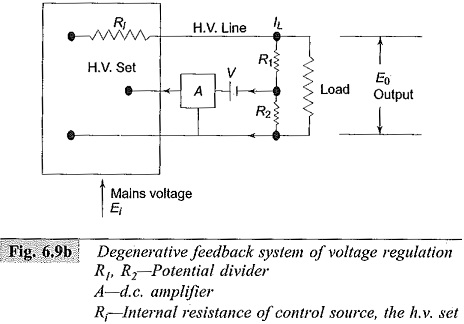
A convenient method of regulating high d.c. voltages is the degenerative feedback system, shown in Fig. 6.9b. The fluctuations in the output voltage are measured by a detecting device, amplified by a d.c. amplifier and fed back into the high voltage set so as to correct for the original fluctuations. The detecting device in the above circuit is the potential divider of ratio β= R1/(R1 + R2). The amplifier is directly coupled and the difference in potential between the tapping on the divider and the amplifier grid voltage is made up by the battery voltage V.
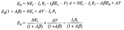
The output voltage E0 is given as follows:
![]()
Where
N = ratio between the output voltage of the h.v. set and the main supply voltage,Ei,
I1 = Load current,
Ri = internal resistance of the h.v. set,
A = gain of the feedback amplifier,
e = amplifier input voltage.
For large values of A
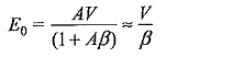
The stabilization ratio
![]()
In practice, values of Aβ of the order of 1000 are common. It can be seen that for given value of A, stabilization ratio can be increased by making β as large as possible.
Stabilities to about 2 parts in 104 in high voltage are easily obtained by this method if load changes are kept small.