Galvanometer Type Recorder:
The D’Arsonval movement used in moving coil indicating instruments can also provide the movement in a Galvanometer Type Recorder.
The D’Arsonval movement consists of a moving coil placed in a strong magnetic field, as shown in Fig. 12.2(a).
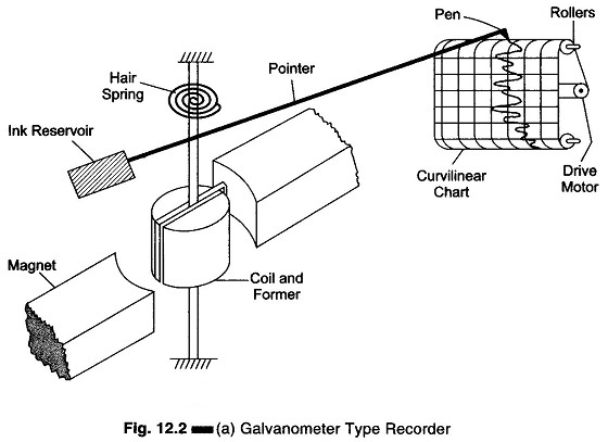
In a galvanometer type recorder, the pointer of the D’Arsonval movement is fitted with a pen-ink (stylus) mechanism.
The pointer deflects when current flows through the moving coil. The deflection of the pointer is directly proportional to the magnitude of the current flowing through the coil.
As the signal current flows through the coil, the magnetic field of the coil varies in intensity in accordance with the signal. The reaction of this field with the field of the permanent magnet causes the coil to change its angular position. As the position of the coil follows the variation of the signal current being recorded, the pen is accordingly deflected across the paper chart.
The paper is pulled from a supply roll by a motor driven transport mechanism. Thus, as the paper moves past the pen and as the pen is deflected, the signal waveform is traced on the paper.
The recording pen is connected to an ink reservoir through a narrow bore tube. Gravity and capillary action establish a flow of ink from the reservoir through the tubing and into the hollow of the pen.
Galvanometer type recorders are well suited for low frequency ac inputs obtained from quantities varying slowly at frequencies of upto 100 c/s, or in special cases up to 1000 c/s.
Because of the compact nature of the galvanometer unit (or pen motor) this type of recorder is particularly suitable for multiple channel operation. Hence it finds extensive use in the simultaneous recording of a large number of varying transducers outputs.
This recorder uses a curvilinear system of tracing. The time lines on the chart must be arcs of radius R (where R is the length of the pointer), and the galvanometer shaft must be located exactly at the center of curvature of a time line arc. Improper positioning of the galvanometer or misalignment of the chart paper in the recorder can give a distorted response, i.e. having a negative rise time or a long rise time. One method of avoiding the distorted appearance of recordings in curvilinear coordinates is to produce the recording in rectangular coordinates. In this design, the chart paper is pulled over a sharp edge that defines the locus of the point of contact between the paper and the recording stylus. The stylus is rigidly attached to the galvanometer coil and wipes over the sharp edge as the coil rotates.
In one of the recorders, the paper used is usually heat sensitive, and the stylus is equipped with a heated tip long enough to guarantee a hot point of contact with the paper, regardless of the stylus position on the chart. Alternatively the paper can be electrically sensitive, in which case the stylus tip would serve to carry current into the paper at the point of contact.
The recorders can work on ranges ranging from a few mA/mV to several mA/mV. These moving galvanometer type recorders are comparatively inexpensive instruments, having a narrow bandwidth of 0 – 10 Hz. They have a sensitivity of about 0.4 V/mm, or from a chart of 100 mm width a full scale deflection of 40 mV is obtained.
In most instruments, the speed of the paper through the recorder is determined by the gear ratio of the driving mechanism. If it is desired to change the speed of the paper, one or more gears must be changed.
Paper speed is an important consideration for several reasons.
- If the paper moves too slowly, the recorded signal variations are bunched up and difficult to read.
- If the paper moves too fast, the recorded waveform will be so spread out that greater lengths of paper will be required to record the variations of the signal. It also makes the task of reading and interpreting the waveforms more difficult.
- Also, the operator can determine the frequency components of the recorded waveform, if he knows how fast the paper has moved past the pen position. The paper is usually printed with coordinates, such as graph
Some recorders contain a timing mechanism that prints a series of small dots along the edge of the paper chart, as the paper moves through the recorder. This time marker produces one mark per second.
These types of recorders are mostly used as optical recorders, and contain a light source provided by either an ultra violet or tungsten lamp.
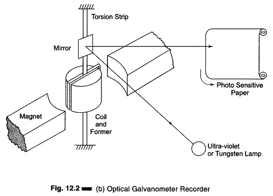
A small mirror is connected to the galvanometer movement and the light beam is focused on this mirror, as shown in Fig. 12.2(b).
The beam reflected from the mirror is focused into a spot on a light sensitive paper.
As the current passes through the coil, the mirror deflects. The movement of the light beam is affected by the deflection of the small mirror, and the spot on the paper also varies for the same reason, thus tracing the waveform on the paper.