Circular Chart Recorder Working Principle:
Circular Chart Recorder Working Principle – As the name implies, the data is recorded on a flat circular chart. The basic assembly of a single pen circular chart recorder is shown in Fig. 12.8.
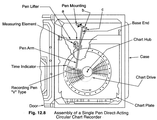
It consists of a measuring element, an operating mechanism, a chart drive, and a recording device, which may all be mounted on a single panel. The chart is usually mounted on a flat supporting plate and fastened in position by spring clips, which prevent it from curling. The measuring element could be a helical pressure tube or any other element. The operating mechanism consists of levers a and b and links c which convey motion from the measuring element to the recording device.
For optimum recording conditions, light uniform pressure, and a smooth flat chart surface must be ensured. The pen arm must be accurately fitted and locked. The chart is driven at a uniform rate by some timing device.
Circular Chart Drive:
A conventional drive assembly consists essentially of a centre chart support spindle and an drive motor. The chart is generally centered and locked around the centre spindle. The chart speed may vary from one rotation in 15 minutes to one rotation in 30 days. A 30 cm circular chart has a maximum time-line length of approximately 100 cm in a revolution, whereas a 15 cm strip chart may move 25 m of chart in the same period.
The various drives for circular charts are classified as follows.
- Mechanical (spring clock drive).
- Pneumatic (air lock drive).
- Electric (synchronous regulated dc motor or motor wound spring).
- Dual powered drive (duplex), i.e. a synchronous motor and spring clock mechanical drive.
- Externally controlled drives.