Block Diagram of Electrical Drives | Advantages | Applications:
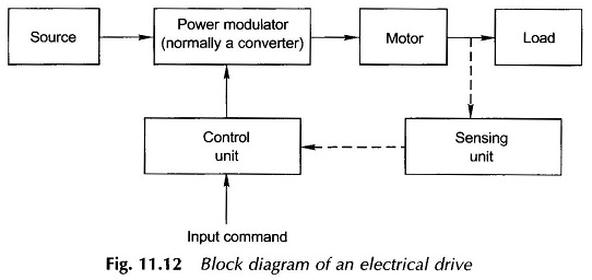
Block Diagram of Electrical Drives – Invention of thyristor led to emergence of semiconductor drives in early sixties. The improvements in converters and development of new drive-control strategies, such as field oriented (or vector) control of ac drives, sliding-mode control, energy saving strategies, etc. brought about another revolution in drive technology and performance. Efforts are also underway to tap alternative/ renewable/new energy sources, especially solar energy. Solar drives have a vital role to play in India particularly in water pumping, air-conditioning, transportation and space applications. Basic Block Diagram of Electrical Drives is shown in Fig. 11.12.
So far variable speed drive applications were dominated by dc motors. Squirrel-cage induction motor which costs approximately one-third of a de motor of the same rating, is quite rugged, maintenance-free, can be built for higher speeds, torques and power ratings. Wound-rotor motors, though costlier than squirrel cage, also have less maintenance and available in higher power ratings. Thus, because of these advantages, ac drives have succeeded in replacing dc drives in a number of variable speed applications.
The PM synchronous motors, stepper motor and switched reluctance motor have also become popular for various applications.
Need for a converter arises when nature of the available electrical power is different than what is required for the motor. Normally, 1-phase and 3-phase 50 Hz ac supplies (except aircraft and space applications where 400 Hz ac supply is used to achieve high power to weight ratio for motors) are used. 1-ph supply is used for economy. The brushless dc motor is being used for replacing dc servomotors for fractional kW range.