Digital Phase Meter Block Diagram and Working Principle:
Digital Phase Meter – The simplest technique to measure the phase difference between two signals employs two flip-flops. The signals to be fed must be of the same frequency. First, the signals must be shaped to a square waveform without any change in their phase positions, by the use of a zero crossing detector. The process of measuring the phase difference of Digital Phase Meter can be illustrated by the schematic diagram shown in Fig. 6.26.
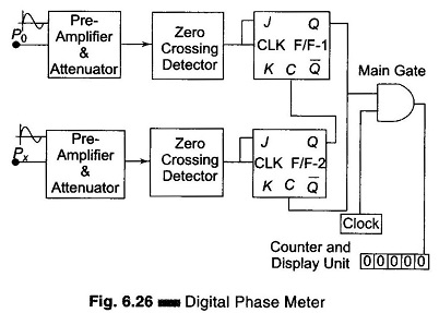
The block diagram of Digital Phase Meter consists of two pairs of preamplifier’s, zero crossing detectors, J-K F/Fs, and a single control gate. Two signals having phases Po and Px respectively are applied as inputs to the preamplifier and attenuation circuit. The frequency of the two inputs is the same but their phases are different.
As the Po input signal increases in the positive half cycle, the zero crossing detector changes its state when the input crosses zero (0) giving a high (1) level at the output. This causes the J-K F/F-1 to be set (1), that is, the output (Q) of F/F-1 goes high. This high output from the F/F-1 enables the AND gate, and pulses from the clock are fed directly to the counter. The counter starts counting these pulses. Also this high output level of F/F-1 is applied to the clear input of F/F-2 which makes the output of the F/F-2 go to zero (0).
Now as the input Px which has a phase difference with respect to Po, crosses zero (0) in the positive half cycle, the zero detector is activated, causing its output to go high (1). This high input in turn toggles the J-K F/F-2, making its output go high. This output (Q) of F/F-2 is connected to the clear input of F/F-1 forcing the F/F-1 to reset. Hence the output of F/F-1 goes to zero (0). The AND gate is thus disabled, and the counter stops counting.
The number of pulses counted while enabling and disabling the AND gate is in direct proportion to the phase difference, hence the display unit gives a direct readout of the phase difference between the two inputs having the same frequency f.
If the input signal frequency is f, then the clock frequency must be 360 times the input frequency for accurate measurements.