Digital Memory Waveform Recorder (DWR):
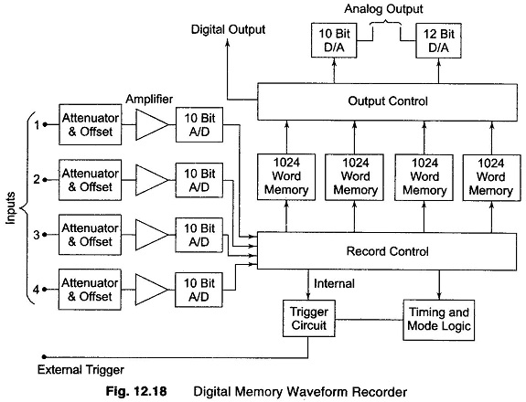
The Digital Memory Waveform Recorder (DWR) shown in Fig. 12.18, provides capability which is difficult to achieve by other methods. The block diagram (Fig. 12.18) is of a unit capable of recording four independent signals simultaneously.
The practical implementation of this concept rests on the ready availability, small size and reasonable cost of digital memories and associated digital hardware.
Consider a signal channel, the analog voltage input signal is digitized by a 10 bit A/10 converter with a resolution of 0.1% (1 part in 1024) and frequency response of 25 kHz.
The total Digital Memory Waveform Recorder (DWR) of 4096 words can be used for a single channel 2048 words can be used for each of the two channels an 1024 for each of the four channels.
The analog input voltage is sampled at adjustable rates (up to 100000 samples per second) and the data points are read into the memory. A maximum of 4096 points are storable in this particular instrument.
(Sampling rate and memory size must be selected to suit duration and waveform of the physical event being recorded. Some models have sampling rates up to 200 MHz.)
Once the sampled record of the event is captured in the memory, many useful manipulations are possible, since the memory can be read without erasing it (non-destructive readout).
By reading the memory out slowly through a digital to analog converter, the original event (which could have been extremely rapid) is reproduced as a slowly changing voltage, that is easy to record permanently in large size on a slow X-Y plotter.
If the memory is read out rapidly and repetitively, an input event which has a one shot transient becomes a repetitive waveform that now may be observed easily on an ordinary oscilloscope (not a storage CRO). The Digital Memory Waveform Recorder (DWR) also may be readout directly (without going through a digital to analog converter) to say, a computer where a stored program can manipulate the data in almost any desired way.
Pre-trigger recording allows the device to record the input signal preceding the trigger point, a unique and often useful capability. In ordinary triggering, the recording process is started by the rise of the input signal (or some external triggering signal) above some preset threshold value. If this threshold is set too low, random noise will trigger the system; too high a threshold prevents recording of the initial rise of the desired signal. The digital recorder can be set to record continuously (new data coming into the memory pushes out the old data, once the data memory is full), until the trigger signal is received. Then the recording process is stopped, thereby freezing in the memory data received prior to the trigger signal.
An adjustable trigger delay allows operator control of the stop point, so that the trigger may occur near the beginning, middle or end of the stored information.
While Digital Memory Waveform Recorder (DWR) waveform recorders are marketed without attached recording devices for analog outputs, such packages are available as a digital memory oscillographs or oscilloscopes.
The usual 40 Hz frequency response of pen/ink recorders can be extended to 20 kHz with a plug-in module using waveform digitizing principles. This principle of waveform digitizing makes direct recording easier. Direct writing instruments of high recording quality are available for recording a very wide range of signals.