Basis of PLC Programming:
1.Processor Memory Organisation:The term processor memory organization refers to how certain areas of memory in a given Basis of PLC Programming are used. Different PLC manufacturers organize their memories in different ways. Even though they do not use the same memory make up and terminology, the principles involved are the same.
Figure 21.66 shows an illustration of memory organization known as a memory map. Every Basis of PLC Programming has a memory map. It need not be the same as the one illustrated. The memory space can be divided into two broad categories the user program and the data table.
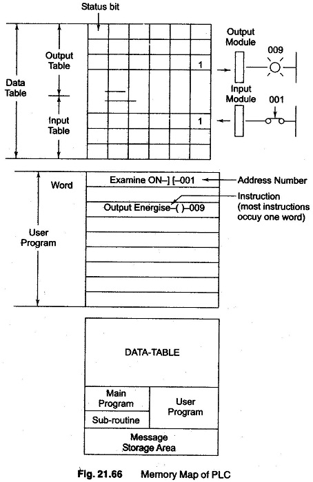
The user program is where the programmed logic ladder diagram is entered and stored. The user program will account for most of the total memory of a given Basis of PLC Programming system. It contains the logic that controls the machine operation. The logic consists of instructions that are programmed in a ladder format. Most instructions require one word of memory.
The data table stores the information needed to carry out the user program. This include, such information as the states of input and output devices, timer and counter values, data storage and so on.
Contents of the data table can be divided into two categories—status data and numbers or codes. Status is ON/OFF type of information represented by 0’s and l’s stored in unique bit locations. Number or code information is represented by group of bits which are stored in unique bytes or word locations.
The data table can be divided into the following three sections according to the type of information to be remembered—The input image table, the output image table, and timer and counter storage.
The input image table stores the status of the digital inputs which are connected to input interface circuits.
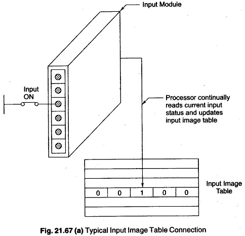
Figure 21.67(a) shows a typical connection of a switch to the input image table through the input module. When the switch is closed the processor detects a voltage at the input terminal and records that information by storing a binary 1 in the proper bit location. Each connected input has a bit in the input image table that corresponds exactly to the terminal to which the input is connected. The input image table is constantly being changed to reflect the current status of the switch. If the input is ON (switch closed), its corresponding bit in the table is set to 1. If the input is OFF (switch open) the corresponding bit is cleared or reset to zero.
The output image table is an array of bits that controls the status of digital output devices which are connected to output interface circuits. Figure 21.67(b) shows a typical connection of a light to the output image table through the output module.
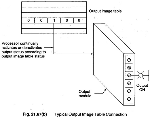
The status of this light (ON-OFF) is controlled by the user program and indicated by the presence of 1 ‘ s (ON) and 0’s (OFF). Each connected output has a bit in the output image table that corresponds exactly to the terminal to which output is connected. If the program calls for a specific output to be ON, it’s corresponding bit in the table is set to 1, if the program calls for the output to be OFF, its corresponding bit in the table is set to 0.
2.Program Scan
During each operating cycle, the processor reads all the inputs takes their values and according to the user program energises or de-energises the outputs. This process is known as a scan. Figure. 21.68 illustrates a single PLC scan, which consists of the 1/0 scan and the program scan.
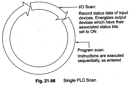
The Basis of PLC Programming scan time specification indicates how fast the controller can react to changes in inputs. Scan time varies with program content and length. The time required to make a single scan can vary from 1 ms to 100 ms. If a controller has to react to an input signal that changes states twice during the scan time it is possible that the PLC will never be able to detect this change.
The scan is normally a continuous and sequential process of reading the status of inputs, evaluating the control logic and updating the outputs. Figure. 21.69 illustrates this process. When the input device connected to address 10114 is closed, the input module circuit senses a voltage and a 1 (ON) condition is entered into the input image table bit 101-14.
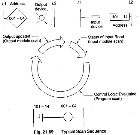
During the program scan, the processor examines bit 101-14 for a 1 (ON) condition. In this case, since input 101-14 is 1, the rung is said to be TRUE. The processor then sets the output image table 001-04 to 1. The processor turns on output 101-14 during the next I/O scan, and the output device (light) wired to this terminal becomes energized. This process is repeated as long as the processor is in the RUN mode. If the input device were to open, a 0 would be placed in the input image table. As a result, the rung would be said to be False. The processor would then set the output image table bit 001-04 to 0 causing the output device to turn off.