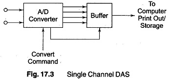
Single Channel Data Acquisition System:
A Single Channel Data Acquisition System consists of a signal conditioner followed by an analog to digital (A/D) converter, performing repetitive conversions at a free running, internally determined rate. The outputs are in digital code words including over range indication, polarity information and a status output to indicate when the output digits are valid.
A Single Channel Data Acquisition System is shown in Fig. 17.3. The digital outputs are further fed to a storage or printout device, or to a digital computer device, or to a digital computer for analysis. The popular Digital panel Meter (DPM) is a well known example of this. However, there are two major drawbacks in using it as a DAS.
- It is slow and the BCD has to be changed into binary coding, if the output is to be processed by digital equipment.
- While it is free running, the data from the A/D converter is transferred to the interface register at a rate determined by the DPM itself, rather than commands beginning from the external interface.
Analog to Digital Converters (A/D):
Analog to digital converters used for DAS applications are usually designed to receive external commands to convert and hold. For dc and low frequency signals, a dual slope type converter is often used. The advantage is that it has a linear averaging capability and has a null response for frequencies harmonically related to the integrating period.
(Generally, the integrating time is selected equal to the period of the line frequency, since a major portion of the system interference occurs at this frequency and its harmonics.)
A/D converters based on dual slope techniques are useful for conversion of low frequency data, such as from thermocouples, especially in the presence of noise. The most popular type of converter for data system applications is the successive approximation type , since it is capable of high resolution and high speed at moderate cost. (For a conversion time of 10 μS, the maximum dv/dt for full scale and 0.1% resolution is about 1 V/ms, which is a considerable improvement.)
Higher speeds are obtained by preceding the A/D converter by a sample hold (S/H). The sample hold is particularly required with successive approximation type A/D converters, since at higher rates of input change the latter generates substantial non-linearity errors because it cannot tolerate changes during the conversion process.
Direct digital conversion carried out near the signal source is very advantageous in cases where data needs to be transmitted through a noisy environment. Even with a high level signal of 10 V, an 8 bit converter (1/256 resolution) can produce 1 bit ambiguity when affected by noise of the order of 40 mV.
Pre–amplification and Filtering:
Many low resolution (8/10 bit) A/D converters are constructed with a single ended input and have a normalised analog input range of the order of 5-10 V, bipolar or unipolar. For signal levels which are low compared to input requirements, amplification may be used in order to bring up the level of the input to match converter input requirements, so that optimum use can be made in terms of accuracy and resolution. The amplifier used has a single ended input or a differential input, as shown in Fig. 17.4.
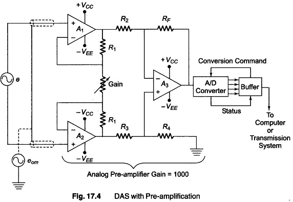
If the signal levels are below a tenth of an mV, or when resolution of 14 bits or 16 bits is needed, the use of differential amplifiers can become a necessity. . When differential output has to be handled from a bridge network, instrumentation amplifiers are employed.
The accuracy, linearity and gain stability specifications should be carefully considered, to ensure the system is not affected by any limitations.
If the input signals are to be physically isolated from the system, the conductive paths are broken by using a transformer coupled or an optocoupled isolation amplifier. These techniques are advantageous in handling signals from high voltage sources and transmission towers. In biomedical applications such isolation becomes essential.
Pre-amplifiers can be coupled with active filters before processing of data, in order to minimise the effect of noise carriers and interfering high frequency components. They effective compensate for transmission sensitivity loss at high frequency and hence enable measurements over an enhanced dynamic frequency range.
Special purpose filters, such as tracking filters, are used for preserving phase dependent data.