Microprocessor Programming:
A program is a set of instructions arranged in the specific sequence to do the specific task. It tells the microprocessor what it has to do. The process of writing the set of instructions which tells the microprocessor what to do is called “Programming“. In other words, we can say that Programming is the process of telling the processor exactly how to solve a problem. To do this, the programmer must “speak” to the processor in a language which processor can understand is called Microprocessor Programming .
Steps Involved in Programming:
Specifying the problem :
The first step in the programming is to find out which task is to be performed. This is called specifying the problem. If the programmer does not understand what is to be done, the programming process cannot begin.
Designing the problem-solution :
During this process, the exact step by step process that is to be followed (program logic) is developed and written down.
Coding :
Once the program is specified and designed, it can be implemented. Implementation begins with the process of coding the program. Coding the program means to tell the processor the exact step by step process in its language. Each Microprocessor Programming has a set of instructions. Programmer has to choose appropriate instructions from the instruction set to build the program.
Debugging :
Once the program or a part of program is coded, the next step is debugging the code. Debugging is the process of testing the code to see if it does the given task. If program is not working properly, debugging process helps in finding and correcting errors.
To write a program, programmer should know :
- How to develop program logic?
- How to tell the program to the processor?
- How to code the program?
- How to test the program?
Flowchart Programming:
To develop the programming logic programmer has to write down various actions which are to be performed in proper sequence. The flow chart is a graphical tool that allows programmer to represent various actions which are to be performed. The graphical representation is very useful for clear understanding of the programming logic.
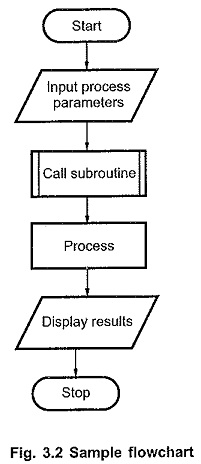
The Fig. 3.1 shows the graphic symbols used in the flow chart of Microprocessor Programming.
Oval : It indicates start or stop operation. Arrow : It indicates flow with direction.
Parallelogram : It indicates input/output operation.
Rectangle : It indicates process operation.
Diamond : It indicates decision making operation. Double sided Rectangle : It indicates execution of pre-defined process (subroutine).
Circle with alphabet : It indicates continuation.
A: Any alphabet
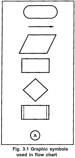
The Fig. 3.2 shows sample flow chart.