8255 Programming and Operation:
The 8255 Programming and Operation are follows
Programming in Mode 0:
The Ports A, B and C can be configured as simple input or output ports by writing the appropriate control word in the control word register. In the control word, D7 is set to ‘1’ (to define a mode set operation) and D6, D5 and D2 are all set to ‘0’ to configure all the ports in Mode 0 operation The status of bits D4, D3, D1 and D0 then determine (refer to Fig. 14.5) whether the corresponding ports are to be configured as Input or Output.
For example in mode 0, if Port A and Port B are to operate as output ports with Port C lower as input, and Port C upper as output, the control word that will have to be loaded into the control register will be as follows.
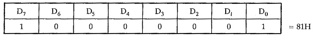
As mernoned earlier, this mode provides simple input and output operations for each of the three ports. No handshaking is required, data is simply written to or read from a specified port.
INPUT MODE :
Fig. 14.6 shows the timing diagram for mode 0 input mode.
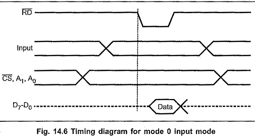
After initialization of 8255 Programming and Operation in the input mode 0, CPU can read data through the input port by initiating read command with proper port address. Read command activates RD signal. Upon activation of RD signal CPU reads the data from the selected input port into the CPU register.
OUTPUT MODE :
Fig. 14.7 shows the timing diagram for mode 0 output mode.
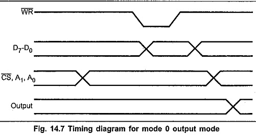
After initialization of 8255 in the output mode 0, CPU can write data into the output port by initiating write command with proper port address. CPU sends data on the data bus and upon activation of WR signal, data on the data bus gets latched on the selected output port.
Mode 0 Configurations :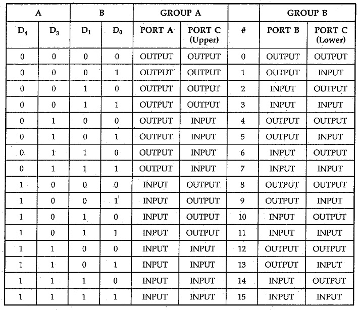 Programming in Mode 1 (Input / Output With Handshake):
Both Group A and Group B can operate in Mode 1, either together, or individually, with each port containing an 8-bit latched Input or Output data port, and a 4-bit port which is used for control and status of the 8-bit port.
When Port A is to be programmed as an input port, PC3 , PC4 and PC5 are used for control. PC6 and PC7 are not used and can be Input or Output, as programmed by bit D3 of the control word. When Port A is programmed as an output port, PC3 , PC6, and PC7 are used for control and PC4 and PC5 can be Input or Output, as programmed by bit D3, of the control word.
When port B is to be programmed as an input or output port, PC0 , PC1 and PC2 are used for control.
Mode 1 Input Control Signals :
STB (Strobe Input) : This is an active low input signal for 8255 Programming and Operation and output signal for the input device. The input device activates this signal to indicate CPU that the data to be read is already sent on the port lines of 8255 port. Upon activation of this signal 8255 loads the data from the input port lines into the input buffer of that port.
IBF (Input Buffer Full) : This is an active high output signal for 8255 and an input signal for input device. This signal is generated by 8255 Programming and Operation in response to STB signal as an acknowledgment to input device. It also indicates to the input device that the input buffer is full and it is not ready to accept next byte from the input device. Therefore input device sends data on the port lines only when IBF signal is not active. The IBF signal is deactivated when CPU reads the data from input buffer of the respective port by activation of RD signal.
INTR (Interrupt Request) : This is an active high output signal generated by 8255. A ‘high’ on this output can be used to interrupt the CPU when an input device is requesting service. The 8255 Programming and Operation sets the INTR when STB signal is ‘one’, IBF signal is ‘one’ and INTE is ‘one’, indicating CPU that the data from the input device is available in the input buffer. This signal is reset by the falling edge of the RD signal i.e. immediately after reading the data from the input buffer.
INTE (Interrupt Enable) flip flop is used to enable or disable INTR (Interrupt request) signal. If INTE flip-flop is set, the interrupt request is generated depending on the status of STB and IBF signals. If INTE flip flop is reset, the interrupt request is not generated, allowing masking facility for the interrupt.
Mode 1 : Port A Input Operation :
Fig. 14.8 (a) (see Fig. on next page) shows Port A as an input port along with the control word and control signals (for handshaking with a peripheral). When the control word (as in Fig. 14.8 (a) is loaded into the control register, Group A is configured in Mode 1 with Port A as an input port. Port A can accept parallel data from a peripheral (like a keyboard) and this data can be read by the CPU. The peripheral first loads data into Port by making the STBA input low. This latches the data placed by the peripheral on the common data bus into Port A. Port A acknowledges reception of data by making IBFA (Input Buffer Full) high. IBFA is set when the STBA input is made low, as shown in Fig. 14.8 (b).
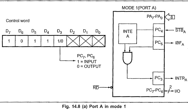
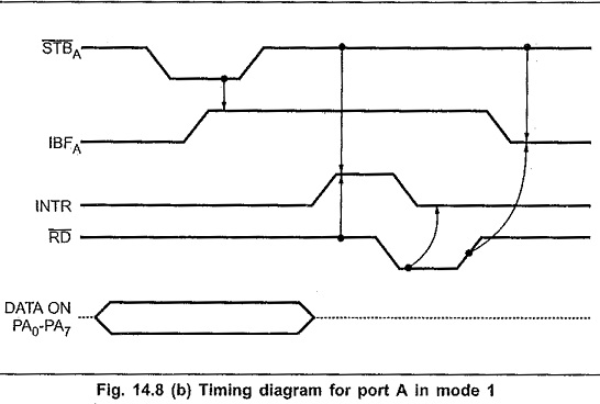
INTRA is an active high output signal which can be used to interrupt the CPU so that the CPU can suspend its current operation and read the data written into Port A by the peripheral. INTRA can be enabled or disabled by the INTEA flip-flop which is controlled by Bit Set-Reset operation of PC4. INTRA is set (if enabled by setting the INTEA flip-flop) after the STBA has gone high again, and if IBFA is high.
On receipt of the interrupt, the CPU can be forced to read Port A. The falling edge of the RD input resets IBFA and it goes low. This can be used to indicate to the peripheral that the input buffer is empty and that data can again be loaded into it.
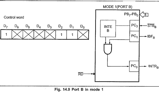
Mode 1 : Port B Input operation:
Fig. 14.9 shows Port B as an input port (when in Mode 1). The timing diagram and operation of Port B is similar to that of Port A except that it uses different bits of Port C for control. INTEB is controlled by Bit Set/Reset of PC2.
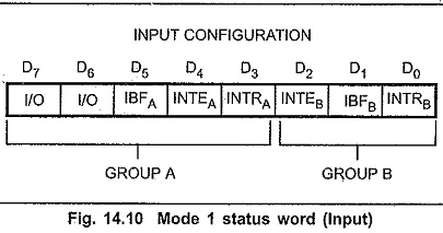
If the CPU is busy with other system operations, it can read data from the input port when it is interrupted. This is often called Interrupt driven I/O. However, if the CPU is otherwise not busy with other jobs, it can continuously poll (read) the status word to check for an IBFA. This is often called Program Controlled I/O. The status word is accessed by reading Port C (A 1 A 0 must be 10, RD and CS must be low).. The status word format when Ports A and B are input ports in Mode 1, is shown in Fig. 14.10.
Mode 1 : Output control signals:
1.OBF (Output Buffer Full) :
This is an active low output signal for 8255 Programming and Operation and input signal for the output device. The 8255 activates this signal to indicate output device that data is available on the output port. Upon activation of OBF signal, output device reads data from the output port and acknowledges it by ACK signal. The OBF signal is activated at the rising edge of the WR signal and de-activated at the falling edge of the ACK signal.
2.ACK (Acknowledge Input):
This is an active low input signal for 8255 and output signal for the output device. The output device generates this signal to indicate 8255 that the data from port A or Port B has been accepted.
3.INTR (Interrupt Request) :
This is an active high output signal generated by 8255 A ‘high’ on this output can be used to interrupt the CPU when an output device has accepted data transmitted by the CPU. The 8255 Programming and Operation sets the INTR when ACK signal is ‘one’, OBF is ‘one’ and INTE is ‘one, indicating that the output device is ready to accept next data byte. This signal is reset by the falling edge of the WR signal i.e. immediately after sending the data to the output port.
INTE (Interrupt Enable) flip-flop is used to enable or disable INTR (Interrupt Request) signal. If INTE flip flop is set, the interrupt request is generated depending on the status of ACK and OBF signals. If INTE flip flop is reset, the interrupt request is not generated, allowing masking facility for the interrupt.
Mode 1 : Port A output operation:
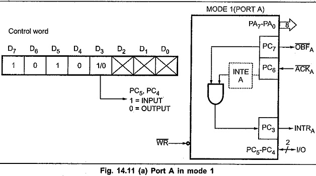
Fig. 14.11 (a) shows Port A configured as an output port (when in Mode 1) along with the control word and control signals (for handshaking with a peripheral). When the control word (as in Fig. 14.11 (a)) is loaded into the control register, Group A is configured in Mode 1 with Port A as an output port The CPU can send data to a peripheral (like a display device) through Port A of the 8255.
The OBFA output (Output Buffer Full) goes low on the rising edge of the WR signal (when the CPU writes data into the 8255). The OBFA output from 8255 Programming and Operation can be used as a strobe input to the peripheral to latch the contents of Port A. The peripheral responds to the receipt of data by making the ACKA input of the 8255 low, thus acknowledging that it has received the data sent by the CPU through Port A. The ACKA low sets the OBFA signal, which can be polled by the CPU through OBFA of the status word to load the next data when it is high again.
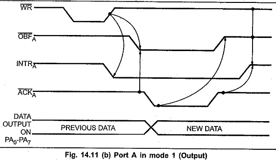
INTRA is an active high output of the 8255 Programming and Operation which is made high. (if the associated INTEA flip-flop is set) when ACKA is made high again by the peripheral, and when OBFA goes high again (see timing diagram in Fig. 14.11). It can be used to interrupt the CPU whenever the output buffer is empty. It is reset by the falling edge of WR when the CPU writes data onto Port A. It can be enabled or disabled by writing a ‘1’ or a’0′ respectively to PC6 in the BSR mode.
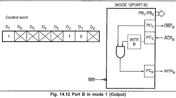
Mode 1 : Port B output operation:
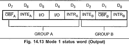
Fig. 14.12 shows Port B as an output port when in Mode 1. The operation of Port B is similar to that of Port A. INTRA is controlled by writing a ‘1’ or a ‘0’ to PC2 in the BSR mode. The status word is accessed by issuing a Read to Port C. The format of the status word when Ports A and B are Output ports in Mode 1 is shown in Fig. 14.13.
Programming in Mode 2 (Strobes Bi-directional Bus I/O):
When the 8255 Programming and Operation is operated in Mode 2 (by loading the appropriate control word), Port A can be used as a bi-directional 8-bit I/O bus using for handshaking. Port B can be programmed in Mode 0 or in Mode 1. When Port B is programmed in mode 1, PC0 – PC2 lines of Port C are used as handshaking signals.
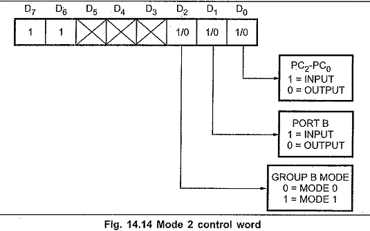
Fig. 14.14 shows the control word that should be loaded into the control port to configure 8255 in Mode 2,
Mode 2 : Control signals:
INTR (Interrupt Request).: A ‘high’ on this output can be used to interrupt the CPU for input or output operations.
Output Control Signals :
OBFA (Output Buffer Full):
This is an active low output which indicates that the CPU has written data into Port A.
ACKA (Acknowledge):
This is an active low input signal (generated by the peripheral) which enables the tri-state output buffer of Port A and makes Port A data available to the peripheral. In Mode 2, Port A outputs are in tri-state until enabled.
INTE 1:
This is the flip-flop associated with Output Buffer Full. INTE 1 can be used to enable or disable the interrupt by setting or resetting PC6 in the BSR Mode.
Input Control Signals:
STB (Strobe Input):
This is an active low input signal which enables Port A to latch the data available at its input.
IBF (Input Buffer Full Flip-Flop):
This is an active high output which indicates that data has been loaded into the input latch of Port A.
INTE 2:
This is an Interrupt enable flip-flop associated with Input Buffer Full. It can be controlled by setting or resetting PC4 in the BSR Mode.
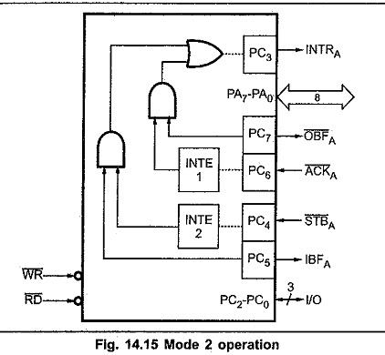
Mode 2 : Port A operation:
Fig. 14.15 (see Fig. on next page) shows Port A and associated control signals when 8255 is in Mode 2. Interrupts are generated for both output and input operations on the same INTRA (PC3) line.
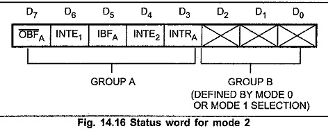
Status Word In Mode 2:
The status word for Mode 2 (accessed by reading Port C) is shown in Fig. 14.15. D7 – D3 of the status word carry information about OBFA, INTE1, IBFA ,INTE2 ,INTRA .The status of the bits D2 – D0 depends on the mode setting of Group B. If B is programmed in Mode 0, D2 – D0 are the same as PC2 – PC0 (simple I/O); however if B is in Mode 1, D2 – D0 carry information about the control signals for Port B (as in Fig. 14.10, or Fig. 14.13), depending upon whether Port B is an Input port or Output port respectively.