Data Logger Operation:
Data Logger Operation – For proper understanding of a Data Logger Operation, it is essential to understand the difference between analog and digital signals. For example, measurement of temperature by a milli voltmeter, whose needle shows a reading directly proportional to the emf generated by the thermocouple, is an analog signal.
However, digital equipment presents a digital output in terms of pulses and involves an electronic pulse counting equipment which counts the number of pulses. The pulses are generated such that each pulse corresponds to the smallest value of the parameter being measured.
These digital signals are precise at all times. Consider the example of temperature. In the case of analog measurements even the accuracy of the potentiometric method is limited by the precision with which the resistance can be subdivided. In the digital method, the electrical signal obtained from the thermocouple is subdivided by an electronic decade circuit and thus the thermocouple voltage can be measured to many places of decimal.
An analog device is capable of measuring with an error of ± 0.5% to ±1%,whereas a digital device can be obtained with an error of any ± 0.01%. An analog instrument responds to a change in input levels in times of the order of 0.25 to 1 s while a digital instrument gives accurate readings in a few hundredth’s of a second, and often many times faster.
One advantage of a digital instrument is that its reading can be recorded by suitable printer.
The Data Logger Operation senses only digital signals and hence analog signals, if any, have to be converted to digital signals. The digital technique is employed because it measures very small (or large) signals accurately and fast.
The recording device may be a printed log or a punched paper tape. The printed output can be either line by line on a paper strip or on a type written page.
Time words are printed at the start of each sequence. Time is recorded in hours, minutes and seconds. Data Logger Operation consists of the channel identity number, followed by polarity indication (+ or —), the measured value (4 or 6 digits) and units of measurement. Sometimes the range may also be indicated.
Basic parts of a Data Logger Operation
- Input scanner
- Signal conditioner
- A/D converter
- Recording equipment
- Programmer
The block diagram of a Data Logger Operation involving all these parts is shown in Fig. 17.24.
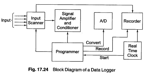
The input scanner is an automatic sequence switch which selects each signal in turn. Low level signals, if any, are multiplied to bring them up to a level of 5 V. If the signals are not linearly proportional to the measured parameter, these signals are linearised by the signal conditioner.
The analog signals are then converted to digital signals suitable for driving the recording equipment (printer or punched paper tape).
The programmer (serialiser) is used to control the sequence operation of the various items of the logger. It tells the scanner when to step to a new channel, and receives information from the scanner, converter and recorder. The real time clock is incorporated to automatic the system. The clock commands the programmer to sequence one set of measurements at the intervals selected by the user.
Input Signals
The input signals fed to the input scanner of the Data Logger Operation can be of the following types.
- High level signals from pressure transducers
- Low level signals from thermocouples
- ac signals
- Pneumatic signals from pneumatic transducers
- On/off signals from switches, relays, etc.
- Pulse train from tachometer
- Digital quantities
The last three signals (5, 6 and 7) are of the digital type and are handled by one set of input scanners and the remaining signals are of the analog type and are handled by a different set of input scanner.
Low level dc signals are first amplified and then conditioned by the law network and finally fed to the A/D converter.
High level signals are fed straight to law network and converter.
The ac and pneumatic signals are first converted to electrical dc signals, conditioned and then converted.
In this manner, all types of signals are converted to a form, suitable for handling by the data logger.
The purpose of the conditioner is to provide a linear law for signals from various transducer which do not have linear characteristics.
Filters are used for noise and ripple suppression at the interface of the output of the transducers and the input of the signal conditioner, since these signals carried by the cables are of very low magnitude. Digital signals are then fed to the digital interface, whereas analog signals are first amplified, linearised and then brought to the analog interface. They are then converted into digital form and finally fed to the digital interface.
-
Input Scanners
Because the scanner select each input signal in turn, the Data Logger Operation requires only one signal amplifier and conditioner, one A/D converter and a single recorder.
Modern scanners have input scanners which can scan at the rate of 150 inputs/s, but the rate of scanning has to be matched with the rate of change of input data, and the time required by the recorder and the output devices to print one output.
Sometimes it is desirable to scan certain parameters at a faster rate and some others at a longer intervals. For such mixed scan rates, the scanning equipment is designed for an interlaced scan operation, in which it is possible to log some parameters at 30 — 60 minutes interval, some every 5 minutes, and others every few seconds.
A scanner, in effect, is a multiway switch which is operated by a scanner drive unit for selecting the circuits. As the switch contacts have to continuously (24 hours/day) deal with low level signals at very, high frequencies, the following requirements (desired characteristics) must be considered in the design of the contacts and their operations.
- Low closed resistance
- High open circuit resistance
- Low contact potential
- Negligible interaction between switch energising signal and input signals
- Short operating times
- Negligible contact bounce
- Long operation life
Although it may not be possible to achieve all these characteristics in one switch, the arrangement selected must satisfy the maximum possible conditions. The various switching elements available commercially are as follows.
- Rotary selector switch
- Electromagnetic operated relays
- Dry Reed type
- Mercury wetted reed type
- Solid state switches
Scanner Drive
The most common arrangement for selecting individual input one after another, is to use a matrix, as shown in Fig. 17.25.
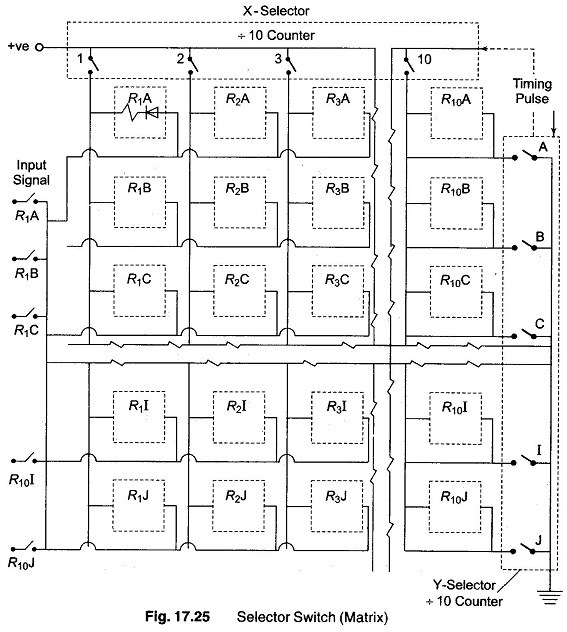
The matrix is formed by using two energising lines, X and Y, corresponding to horizontal and vertical respectively, each having 10 contacts. Hence a 10 x 10 matrix is formed, giving 100 input channels per scanner unit or module. The only relay at the intersection of the energised X and Y lines is operated. The timing pulse thus consists of two signals, one for the X line and the other for the Y line. Each relay has a diode in series with its coil, to prevent other relays being energised via other paths.
The energising signals, i.e. the timing pulses are normally developed using counter circuits, which start off selecting one of the X lines, and then all the Y lines in sequence. After this cycle is completed, the next X line is selected and again all the Y lines are selected in turn. In this way each input is scheduled in turn. Generally, transistor switches are used to select the input relay.
As the measuring transducers and sensing elements are located at distances of about 300 — 400 m away from the scanner, the electrical interference, i.e. the electrical voltage induced in the signal lines can swamp an actual signal voltage.
The most common method to eliminate or reduce the effect of common mode noise is to use an amplifier with a floating input.
Although the effect of noise is practically eliminated as the low level signals, these signals have to be amplified further to a suitable level to drive the A/D converter. Hence the signal amplifier should have the following characteristics.
- Precise and stable dc gain
- High signal to noise ratio
- Good linearity
- High input impedance
- High CMRR
- Low output impedance
- Low dc drift
- Wide band width
- Fast recovery time
-
(Signal) Input Conditioning
Since Data Logger Operation give their readout in the units of measurements concerned, there are two requirements:
- Scaling linear transducers
- Correcting the curvature of a non-linear transducer, such as a thermocouple
Linear inputs can be dealt with in two ways.
- The simplest is to provide individual resistance attenuation on each input in order to reduce the transducer output level, where the scale factor is an integral power of ten. For example, if a particular transducer has a full scale of 10 mV for a pressure of 500 kg/cm2, we can reduce the value to one half by the use of an attenuator, such that 500 kg/cm2 may be represented by 5 mV. If the system is to have a resolution of 1 kg/cm2, the A/D converter must have a resolution of 10 pV. This technique is limited only by the sensitivity of the A/D converter.
- The second method is to change the sensitivity of the A/D converter. But since each input may require a different scale factor, this is not convenient as an input attenuation technique.
The signal can be linearised at any one of the following three places.
- In the analog stage before conversion
- In the conversion process
- Digitally after conversion
The first method is not suited to low level voltages, as it requires some form of amplification. The signal conditioner may be placed between the scanner and the converter. But, each type of transducer requires individual linearising circuits.
The third method requires a storage capability and a computer processing technique. The most satisfactory is the second method, whereby linearisation is built into the conversion process.
-
A/D Converters
These have been discussed already.
-
Recorders
The output from the Data Logger Operation can be printed on any of the following.
- Typewriter
- Strip printer and/or digitally recorded on punched tape or magnetic tape for further analysis in a digital computer.
The typewriter provides a conventional log sheet with tabulated results, and prints in two colours.
The signals obtained from the A/D converters are applied to the electro- magnetic operated levers of a typewriter. Plus, Minus, characters which can be printed one at a time, decimal point shift, line shift, type colour and spacing are controlled by the EM solenoids which are energised from the programmer unit. Punched paper tape or magnetic tape is used when the recorded data is to be further analysed or where the rate of data acquisition is too great for a printer.
-
Programmer
This can be considered as an automatic sequence switch which controls the operation of all other units of the data logger. The sequential operations performed by a programmer are as follows.
- Set amplifier gain for individual input, i.e. gain of the amplifier has to be so adjusted that for a maximum value of input signal, the A/D converter records a full scale reading.
- Set linearization factor so that the adjusted output from the signal amplifier is directly proportional to the measured quantity.
- Set high and low alarm limit
- Initiate alarm for abnormal condition
- Select input signal scanner switching is set normally by a timing pulse to select the reset input.
- Start A/D conversion
- Record reading channel identify and time (in order that the readings may be identified at a later stage, a number identifying that the input has been normally recorded, with the actual reading and the time during the beginning of each complete scan).
- Display reading
- Reset logger. (At the end of cycle the A/D converter sections of the logger are reset to their initial conditions and the cycle, starts again.)