8087 Numeric Data Processor:
The 8087 Numeric Data Processor (NDP) is called a high-speed math co-processor. This math co-processor is also known as Numeric Processor Extension (NPX) or Numeric Data Processor (NDP) or Floating Unit Point (FUP). The 8087 is available in 40-pin DIP packages in 5 MHz, 8 MHz, and 10 MHz versions and it is compatible with 8086 and higher-version processors.
Block Diagram of 8087
Figure 7.40 shows the block diagram of the internal architecture of 8087.
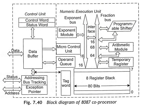
The 8087 co-processor consists of
- Control Unit (CU) and
- Numeric Execution Unit (EU).
Control Unit (CU) This unit is used to synchronize the operation between the main processor and co-processor. The control unit receives the instruction opcode, and then it decodes the instructional opcode and reads or writes operands from memory. The control unit provides the communication between the processor and memory, and it also coordinates the internal coprocessor execution. This unit continuously monitors the data bus to find instructions for the 8087 co-processor.
The control unit of 8087 maintains a parallel queue just like the queue of the main processors. The control unit also always monitors the B̅H̅E̅/S7 line to detect the processor type that is either 8086 or 8088. According to the main processor, the queue length will be adjusted. For the 8086 processor, the queue length will be 6 bytes, but for 8086 processor, the queue length will be 4 bytes. The 8087 uses the queue status input pins QS0 and QS1 to identify the instructions fetched by the main processor. All instruction codes of 8087 have 11011 as the most significant bits of their first code byte. Actually, the main processor identifies the co-processor instruction using the ESCAPE code. Once the main processor recognizes the ESCAPE code, it sends a trigger signal so that the execution of the numeric data processor instruction starts in 8087.
During execution, the ESCAPE code identifies the co-processor instruction which can be operated with or without a memory operand. If the co-processor instruction requires a memory operand that will be fetched from memory then the physical address of the memory location will be computed using any one of the addressing modes in 8086 and a dummy read cycle must be initiated by the main processor. Thereafter, the 8087 co-processor reads the operand and proceeds for execution. If the co-processor instruction does not require any operand then the instruction can be directly executed. After execution of the instruction, the 8087 is ready with the execution results and the control unit obtains the control of the bus from 8086 and executes a memory write cycle to write the results at the specified memory location. The control unit consists of a control word, a status word and a data buffer which are explained later.
Numeric Execution Unit (NEU) The Control Unit (CU) consists of a data bus buffer, status and control register and the Numeric Execution Unit (EU) has eight data register stacks, microcode control unit and a programmable shifter. These units duplicate the functions performed by the microprocessor control and ALU blocks. The 8087 NEU and CU can work independently. The CU works to maintain synchronization with the main 8086/8088 processor while the NEU is performing numeric operations.
The numeric extension unit performs all operations that access and manipulate the numeric data in the co-processor’s registers. In NEU, the numeric registers are 80 bits wide and the numeric data is routed by a 64-bit mantissa bus and a 16-bit sign/exponent bus. The Numeric Execution Unit (NEU) executes all 8087 numeric data processor instructions such as arithmetic, logical, transcendental and data-transfer instructions. The operation of CU and NEU is asynchronous with each other. The internal data bus is 84 bits wide which consist of 68-bit fraction, 15-bit exponent and a sign bit.
When the NEU starts execution of an instruction, it always pulls up the BUSY signal. Usually the BUSY signal is connected with the T̅E̅S̅T̅ input signal of the 8086 processor. When the BUSY signal of 8087 is verified by the main processor, the CPU is able to distinguish that the instruction execution is not yet completed. Therefore, 8086 must he waiting till the BUSY pin of 8087 or the T̅E̅S̅T̅ input pin of 8086 becomes low. The microcode control unit generates the control signals which are required for execution of the instructions. The programmable shifter is used for shilling the operands during the execution of instructions. The data bus interface is able to connect the internal data bus of 8087 with the main processor data bus.
Registers of 8087 Co-processor The 8087 co-processor has additional 13 registers to the 8086 and higher processors such as eight 80-bit floating point data registers, a control register, a status register, a tag register, an instruction pointer and a data pointer register. Figure 7.41 shows the registers of 8087 numeric data processor and 8086/8088 main processor.
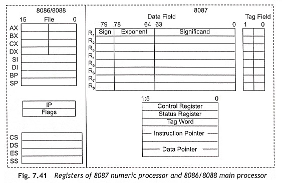
Floating Point Data Registers The 8087 has eight 80-bit individually addressable data registers organized as stack registers R1 to R8 as shown in Fig. 7.41. The mathematical operations are performed in these registers. 8087 instructions can access these registers independently.
The data registers are theoretically divided into three fields such as sign (1-bit), exponent (15-bits) and significant (64-bits). The actual use of these fields varies with the type of data being operated with the instruction. When the 8087 receives numeric data words, it stores and holds them in a format called temporary real form. This number is expressed as the product of a 64-bit significant base and a 15-bit exponent and the Most Significant Bit (MSB) of the register is reversed as a sign bit to represent either a positive or a negative number The 8087 instructions automatically convert data into this format when loading the registers and return back to the other format when returning them to the system memory.
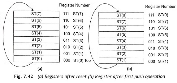
These registers can be represented as ST(0), ST(1), ST(2), ST(3) ST(4), ST(5) ST(6), and ST(7). When the 8087 co-processor is reset, ST(0) becomes the top of the stack and ST(1) refers to the next register in the stack and other registers will be referred accordingly as shown in Fig. 7.42 (a). After the first push operation, the register 000 becomes ST(1) and the register 111 refers ST(0). Similarly, other registers are referred as shown in Fig. 7.42 (b). During programming, any register can be used as the top of the stack and other registers will be referred according to their position.
Control Word Register The 16-bit control word register is used to control the operation of the 8087. The control word register bits can select the required data processing options such as precision control, rounding control and infinity control. Figure 7.43 shows the format of the control word register. The bits D5-D0 are used for masking the different exceptions. An exception may be masked by setting the respective bit in the control word register. The IEM bit is used as a common interrupt mask for all the interrupts. When IEM is set, all the exceptions generated will be masked and the execution may continue.
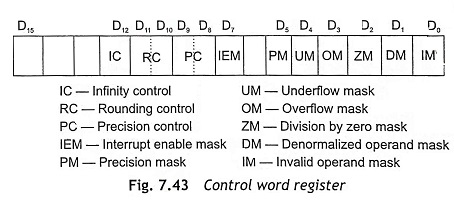
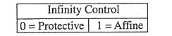
IC Infinity control selects either affine or protective infinity. Affine allows positive and negative infinity, while protective assumes infinity is unsigned. Hence the Infinity Control (IC) provides control over the number size on both sides, i.e., either +∞ or – ∞.
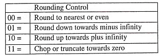
RC Rounding control determines the type of rounding as given below.
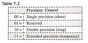
PC Precision control bits control the precision of the result as given in Table 7.2.
Status Register The operation of the 8087’s status register is similar to the 8088’s flag register. The co-processor status register contains the conditional code bits and the floating point flags as shown in Fig. 7.44. During executing an instruction, the 8087 co-processor generates six different exceptions. These are reflected in the status register format. Whenever any exception is generated, an interrupt take place to the CPU provided it is not masked. Then the 8086 processor will respond if the interrupt flag of the CPU is set. When the exceptions are masked, the 8087 continues the execution. Therefore, the status register reflects the over all operations of the 8087 co-processor.
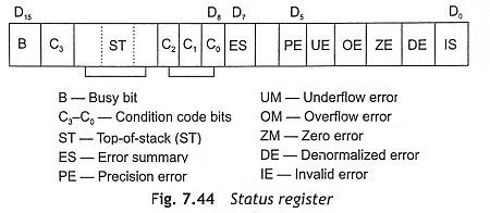
B Busy bit (B) indicates that 8087 co-processor is busy executing an instruction. Busy can be tested by examining the status or by using the FWAIT instruction.
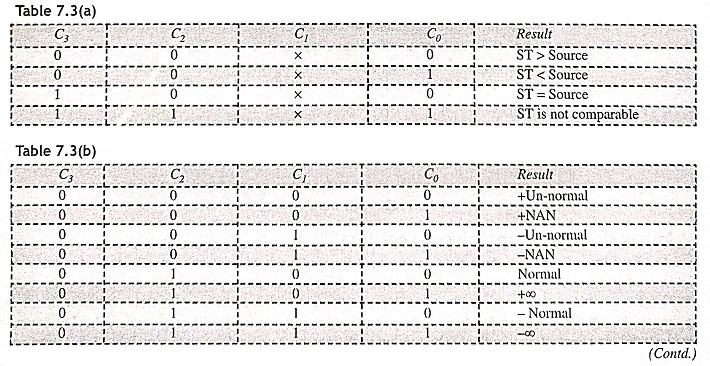
C3-C0 Condition code bits indicates conditions about the co-processor as given Table 7.3(a) and Table 7.3(b)
ST Top of the stack (ST) bit shows the current register address as the top of the stack.
ES Error summary bit is set if any unmasked error bit (PE, UE, OE, ZE, DE, or IE) is set. In the 8087 co-processor, the error summary is also caused a co-processor interrupt.
PE Precision error indicates that the result or operand executes selected precision.
UE Under flow error indicates that the result is too small to fit in the specified format 8087 generates these exceptions. When this exception is masked, the 8087 denormalizes the fraction until the exponent fits in the specified destination format.
OE Over flow error indicates that result is too large to represent in the specified format. If this error is masked, the 8087 co-processor generates infinity for an overflow error.
ZE The zero error indicates if any non-zero finite operand is divided by zero. In this case the (divisor is zero while the divided is a non-infinity or non-zero number. The zero error bit indicates that the result is infinity, even if the exception is masked.
DE The denormalized error indicates, if at least one of the operand is denormalized. This error may be generated, if the result is denormalized. When this bit is masked, 8087 continues the exception normally.
IE Invalid error shows a stack overflow or a stack underflow and uses “NAN” as operand. For example, if we find the square root of a negative number, this flag error will be generated.
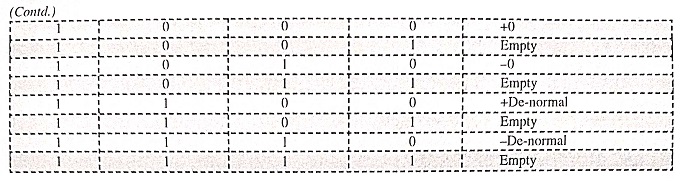
TAG Register The tag register contains several groups of 2 bits that can determine the state of the value of the eight 80-bit stack registers as valid, zero, special or empty. Tag register is a two-bit register called TAG field as shown in Fig. 7.45. The tag word register presents the entire TAG field to the CPU. The tag values are 00 = valid, 01 = zero, 10 = special and 11 = empty.
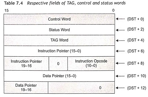
Instruction and Data Pointer Registers The instruction and data pointer registers are used to hold the information about the last executed floating point instruction. Actually, the information is address of instruction, op-code and operand address. Prior to execution of a mathematical instruction, the 8087 forms a table in the memory. The table contains the instruction address in the fields of the instruction pointers, the opcode of the instruction, and operand address in the field of data pointers. The TAG word, status word, and control word will also be present in their respective fields as shown in Table 7.4. Therefore, the instruction pointer and the data pointer registers contain the address of the currently executed instruction and the corresponding data.