80287 Numeric Data Processor:
The 80287 Numeric Data Processor is an advanced version of its predecessor, the 8087, and it is specially designed to operate with the processor 80286. The 80287 provides about 70 additional instructions to the instruction set of 80286. These instructions are executed coherently by 80287 under the control of 80286. The 80287 co-processor instruction set can support integer, floating point, BCD, trigonometric and logarithmic calculations. Like 8087, the 80287 is designed using HMOS technology and it is available in a 40-pin DIP package. The block diagram of the internal architecture of 80287 is shown in Fig. 7.50. The internal architecture of 80287 consists of three sections such as
- Bus Control Logic,
- Data interface and Control Unit, and
- Floating Point Unit.
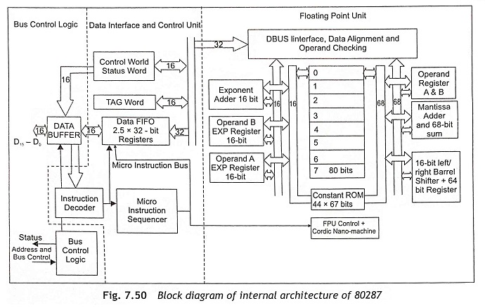
Bus Control Logic The bus control logic controls the interface between the internal data bus of 80287 and the 80286 bus though data buffer.
Data Interface and Control Unit The data interface and control unit consists of status word, control word, TAG word, error pointers, DATA FIFO, instruction decoder and a micro-instruction sequencer. The status word represents the present status of the 80287 co-processor. The control word is used to select any processing options provided by the 80287 co-processor and it is programmed by the main processor. The TAG word is used to improve the performance of 80287 Numeric Data Processor by maintaining a record of empty and non-empty register locations. The error pointer points to the address of the instruction which generates the exception. The instruction decoder and micro-instruction sequencer decodes and forwards the instructions to the floating point unit for execution.
Floating-Point Unit The floating-point unit is the actual data-processing section of the 80287 Numeric Data Processor. This section consists of DBUS interface, data alignment and operand checking, exponent adder, operand registers (A and B), mantissa adder, sum register, 16-bit left/right barrel shifter, operand A and B exp registers. The data bus interface, data alignment and operand checking section is used to check the alignment and validity of the data. Whenever any error is found, a suitable error exception must be generated by the 80287. Usually the eight 80-bit stack registers are used to store operand data. The 80-bit stack registers always maintain 80-bit operands which are required for 80287 operations. The data bus of the floating-point unit consists of 84 bits. The lower 68 bits are mantissa data bit and the next 16 bits are used for exponent. The exponential operand registers A and B are used to store the operands in exponential form. The barrel shifter is used to shift the data which is required for execution.
Status Word The status word is a set of 16 flags which reflects the current status of 80287 as shown in Fig. 7.51. The operations of the various flags are explained below:
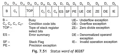
B Flag The BUSY flag has the same status as ES flag. This is used to maintain the compatibility with 8087.
TOP The D13, D12 and D11 bits are used to select one of the eight stack registers as a stack top. If TOP is 000, Register 0 is the top of stack. When TOP is 111, Register 7 is the top of stack. Similarly other registers will be selected depending upon the status of TOP.
C3, C2, C1 and C0 The condition code bits C3, C2, C1 and C0 are similar to the flags of a main processor. Usually, these bits are modified depending upon the result of the execution of arithmetic instructions.
ES This is the error summary bit. If an unmasked exception is generated, it is set.
SF This bit is used as stack flag. When the operation becomes invalid due to stack overflow or underflow, the stack flag is set.
Exception Flags All exception flags are depicted in Fig. 7.51. These are used to show the generation of an exception when 80287 is executing.
Control Word The control word is used to select any processing options of the 80287 co-processor. The control word the 80287 co-processor is shown in Fig. 7.52.
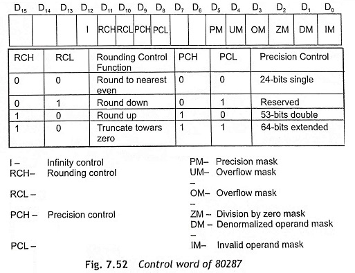
Masking Bits The six masking bits (PM, UM, OM, ZM, DM and IM) are used to mask the six exceptions as shown in the status register. When the masking bit is, ‘1’ , the respective exception is masked.
Precision Control Bits The precision control bits are used to set the internal precision of 80287.
Rounding Control Bits The rounding control bits are used to set rounding operation in arithmetic and transcendental instructions.
Infinity Control Bit The infinity control bit is programmed for compatibility with 80287. This is initialized to zero after reset.