What is System Management Mode (SMM) of the Pentium Processor?
In system management mode, the high power is used up by the Pentium processors. In this mode, the Pentium processors use SMI# (input) and SMIACT# (output) signals. The Pentium can only leave SMM after execution of RSM instruction. In SMM, the SMI# is used as an interrupt.
System Management Mode (SMM) RAM
Generally, the system management mode uses a battery-backed up SRAM at addresses 30000H to 3FFFFH. Usually, this covers up some DRAM addresses. Whenever the SRAM is used, the DRAM must be disabled in the system management mode and the SRAM must be disabled after exiting the system management mode. The SMIACT# signal may be used for this purpose. Figure 12.36 shows the SMM structure supported by the Pentium.
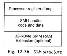
In this operating mode, the Pentium processor operates in an extended real mode. The difference between the normal real mode and an extended real mode is that the SMM address space is not limited to 1 Mbyte, as the offset registers can use 32-bit length. NMI and INTR will not provide any service until SMM has been exited.
Dual Processing
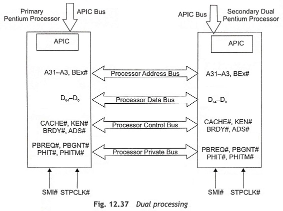
Figure 12.37 shows the dual processing of two Pentium processors. It is clear from Fig. 12.37 that the private bus between two CPUs consists of PBREQ#, PBGNT#, PHIT# and PHITM# signals. The control bus has CACHE#, KEN#, PHIT# and PHITM# signals. The processor address bus consists of BEX# and A31-A3. D63-D0 are used as processor data bus. During dual processing, one processor is used as the primary Pentium, the other processor is the secondary or dual Pentium. After reset, only the primary Pentium processor starts to execute. After that, the primary Pentium processor checks the presence of the secondary Pentium processor in the system. If the secondary Pentium processor is present, the primary Pentium processor can enable the private bus and on-chip APICs.
Bus Arbitration One Pentium processor is used as the Most Recent Master (MRM) and the other Pentium processor is the Least Recent Master (LRM). When the LRM wants to use the bus, the following sequence of operations will happen:
Step 1 The least recent master asserts PBREQ# signal.
Step 2 The most recent master completes any pending bus cycles and grants the bus.
Step 3 The most recent master asserts PBGNT# signal.
Step 4 The least recent master becomes the new MRM. After that LRM controls the signals to the common L2-cache, main memory and I/O devices.
On-Chip Advanced Programmable Interrupt Controllers Each Pentium processor has an on-chip Advanced Programmable Interrupt Controller (APIC), which is enabled by the active high voltage level on the APICEN pin during reset. Before using the APIC, the BIOS must be used to initialize the APIC. In a dual Pentium system, the APICs of primary and secondary Pentium processors must be enabled. The interrupt subsystems of the two Pentiums appear as a single interrupt system to the computer system.

Two APICs of primary and secondary Pentium processors are communicated by the PIC bus, which consists of PICD0, PICD1, and PICCLK signals as depicted in Fig. 12.38. Usually, external interrupt request signals are fed to the 8259A PIC (Programmable Interrupt Controller) and after that interrupts are applied to the external I/O APIC (82489DX). The output signals of I/O APIC are distributed to the on-chip APICs of primary and secondary Pentium processors. The 8259A (PIC) is only incorporated in the circuit for compatibility features. The local APICs process local interrupts on the LINT0 and LINT1 pins. Actually, LINT0 and LINT1 pins are NMI and INTR in a single processor system.
Performance of Pentium Processor The Pentium has a time stamp counter, a control and event select register. and two programmable event counters. These counters have specific pins associated with them and allow programmers to measure the code execution time and performance parameters.