Components of Hydroelectric Power Plant:
Components of Hydroelectric Power Plant (or) Hydel power plant are
- Reservoir
- Dam
- Trash rack
- Surge tank
- Fore bay
- Pen stock
- Spill way
- Power house
- Draft tube
Reservoir:
The main purpose of a reservoir is to store the water during rainy season and to supply the same during dry season. Reservoir is the basic requirement of Hydel power plant. Reservoir may be artificial reservoir (or) natural such as lake. Artificial reservoir are built by constructing a dam across the river. Reservoir stores water, which will be used to run the turbine to produce electricity. Water surface in the storage reservoir is known as head race.
Dam:
A dam is a structure built at a suitable location across the river. The main purpose of the dam is to collect water, store and to increase the height of the water level which ultimately increases the reservoir capacity. The dam also increases the working head of power plant. The basic requirement of dam is economy, safety, should be capable of resisting pressure of water and should be stable on all conditions.
A dam is a solid barrier, generally impervious in nature, constructed across a river or a stream. It holds up the flow of water to form a reservoir on the upstream side. Depending upon the quantity of water to be stored, the design of the dam is carried out and the water level is fixed. Provision is made for regulating the flow and also for allowing the excess water to discharge into the river.
Purpose of dams:
Dams are constructed for any one or more of the following purposes:
- Irrigation.
- Generation of hydro-electric power.
- Flood control.
- Navigation.
- Domestic and Municipal purposes.
- Industrial use.
- Recreation.
- Wild life conservation.
- Reclamation of low lying lands, etc.
General terminology:
1. Ayacut: This is the area to be irrigated by a dam. The ayacut for dam is usually expressed in hectares.
2. Catchment Area: It is a rainfall area which always feeds to a reservoir or lake. It is also known as watershed. The catchment area is expressed in square kilometers.
3.Freeboard: The difference in level between the top of the dam (crest) and the maximum waterlevel is called Freeboard.
4. Full Reservoir Level (F.R.L.): This is the water level in the reservoir during normal supply in the river.
5. Maximum Water Level (M.W.L.): This is the level of water in the reservoir during excess supply in the river (i.e.,) during rainy seasons. This is also termed as Highest Flood Level (H.F.L.), since the supply level is maximum during floods.
6. Spillway: It is the overflow portion of a dam, over which surplus discharge flows from the upstream to the downstream.
7. Upstream and Downstream: In dams, the side on which water gets collected is the upstream and the other side is the downstream side.
Selection of dam site
Following are the factors considered while selecting a site for a dam:
- The river valley at the dam site should be as narrow as possible and should open out upstream to provide a reservoir.
- The site should preferably have good soil for foundation.
- The sediment load in the stream should be as little as possible.
- Suitable location for spillway should be available.
- It is necessary for economic feasibility that the bulk of the materials required for the dam be available in close vicinity of the site.
- The value of the property and land submerged by the proposed dam should be low, in comparison to the benefits expected from the dam.
- It is economical if the site has, in the near vicinity, an access road, electric line, water supply, etc.
Types of dams
Dams may be classified into a number of different categories, depending upon the purpose of the classification. However, it is convenient to consider three broad classifications; according to use, hydraulic design and materials comprising the structure.
1. Classification according to use
Dams may be classified according to the functions, which they are to serve, such as storage, diversion or detention.
Storage dams: These dams are constructed to impound water in periods of surplus supply (i.e, during rainy season) for use in periods of deficient supply.
Diversion dams: Diversion dams are constructed to provide head for carrying water into ditches, canals or other conveyance systems to the place of use.
Detention dams: Detention dams are constructed to retard flood runoff and minimize the effect of sudden floods. The water is temporarily stored and released gradually at a safer rate.
2. Classification according to hydraulic design
According to this classification, dams may be classified as over flow or non-overflow dams.
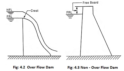
Overflow dams: Overflow dams are designed to carry discharge over their crests. They must be made of materials, which will not be eroded by such discharges.
Non-overflow dams: In non-overflow dams, the crest of the dam is kept sufficiently above the H.F.L. in such a way that they are not overtopped.
3. Classification according to materials used
Based on materials used for construction, dams may be classified into
- Rigid dams
- Non-rigid dams.
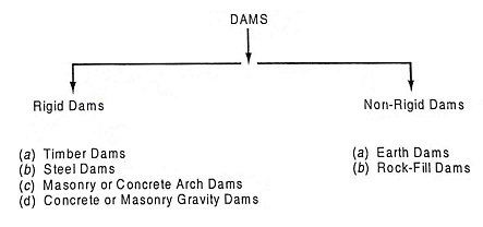
Rigid Dams:
(a) Timber dams are generally constructed for temporary requirements. The height of the dam may be upto 10 m. The maintenance charges are high in comparison with other types. They are suitable for places where timber is available in plenty.
(b) Steel dams are constructed upto a height of 20 m. The face that holds water is made of steel plates and buttresses support them.
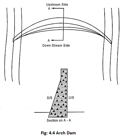
(c) Arch dams may be constructed of masonry or concrete and are curved in plan. The convex face of the arch is on the upstream side. This arrangement helps to transmit the major part of the forces acting on it, by arch action, to the abutments in the rock forming walls of the gorge. Arch dams are suitable for narrow gorge with sound rock.
(d) A Buttress dam is that dam in which stability of dam against external forces is obtained by transferring the water pressure to the supporting buttresses.
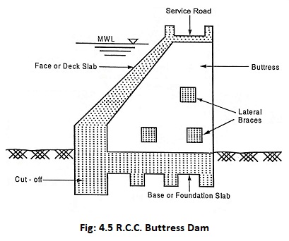
The buttresses are thin walls of triangular profile with a sloping upstream face and usually are spaced at equal intervals along the length of the dam. The upstream face which contributes the water tightness may be in the form of a simple thin slab (Deck slab type buttress dams), thickened buttress heads, plates or arches, vaults of reinforced concrete. A system of cross bracing between buttresses of reinforced concrete beams provides lateral stiffness.
(e) A Gravity dam is a dam proportioned such that, its own weight provides the major resistance to the forces exerted upon it. This type of dam is the most permanent one and it is very commonly used. Gravity dams are constructed with concrete or masonry.
The various forces acting on the gravity dams are;
| (i) | Water pressure | The water collected on the upstream side of the dam exerts pressure on the dam. This is the major external force acting on the dam. |
| (ii) | Self-weight of dam | This is the major resisting force of the dam. |
| (iii) | Uplift pressure | The water that seeps through the foundation and body of dam exerts an upward pressure on the dam. This is called as uplift pressure. |
| (iv) | Silt pressure | The silt deposited on the upstream side of the dam exerts pressure on the dam. This is known as silt pressure. |
| (v) | Wind pressure | This is the minor external force acting on a dam. |
Cross sectional details of a gravity dam
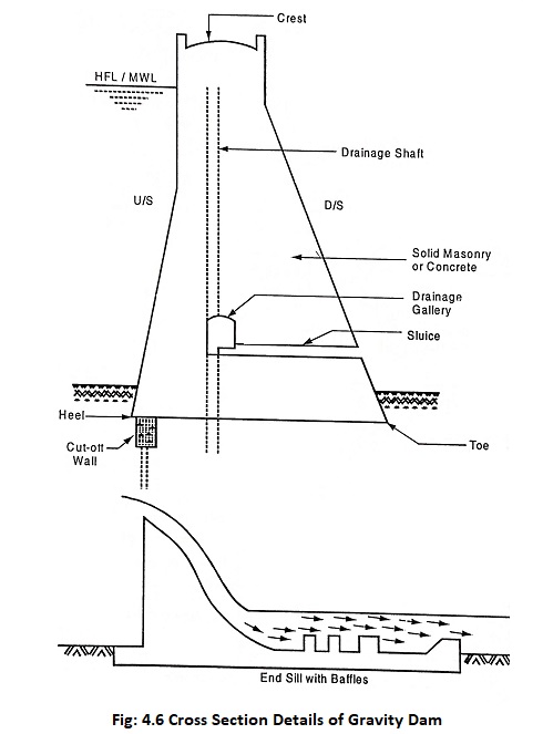
The various components of gravity dam are listed below:
| Crest | This is the top surface of the dam on which the roadway is constructed. |
| Spillway | This is an overflow portion of the dam which discharges excess water (floods) that cannot be stored safely in the dam. A spillway must have the capacity to discharge major floods without damage to dam. |
| Supply Sluices | These are the openings provided in the dam through which water flows from upstream side to downstream side. A sluice gate is used to open or close the openings which is operated either manually or by hydraulic pressure. |
| Drainage Gallery | It is an opening provided in the dam for the purpose of draining the water that seeps through the body of the dam. |
| Cut-off wall | Cut-off wall is a wall constructed below the base of the dam to cut off seepage water. It is also known as core wall. |
| Energy Dissipators | These are the structures provided at the toe of the dam to dissipate the energy of flood water. They may be in the form of curved buckets, baffle blocks etc. |
Non-rigid dams:
(a) Earth dams
Earth dams are constructed with the naturally available soils and gravels. These dams are constructed upto moderate heights. They may be either homogeneous type or zoned embankment type.
(i) Homogeneous Type: A purely homogenous type of dam is composed of a single kind of material. The material comprising the dam must be sufficiently impervious to provide an adequate water barrier and the slopes must be relatively flat for stability.
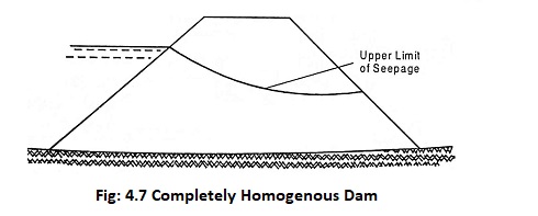
The modified homogenous sections are designed with either rock-toe or filter drains for drainage.

(ii) Zoned Embankment Type: The most common type of a rolled earthfill dam section is that in which a central impervious core is flanked by zones of materials considerably more pervious. The pervious zones enclose, support and protect the impervious core: the upstream pervious zone affords stability against rapid draw down and the downstream pervious zone acts as a drain to control the line of seepage. The pervious zones may consist of sand, gravel, cobbles or mixture of these materials.
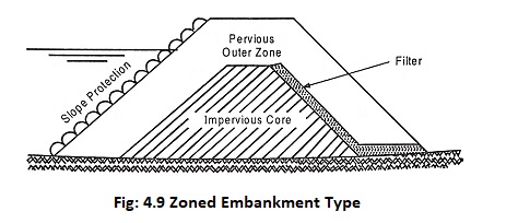
The upstream slope of earth dams must be protected against destructive wave action. Usual types of surface protection for upstream slope are rock riprap, either dry-dumped or hand-placed, and concrete pavement.
(b) Rock fill Dams
In rockfill dams, the principal structural material is rock either dumped or compacted in layers, with sealing provided by an impervious membrane.
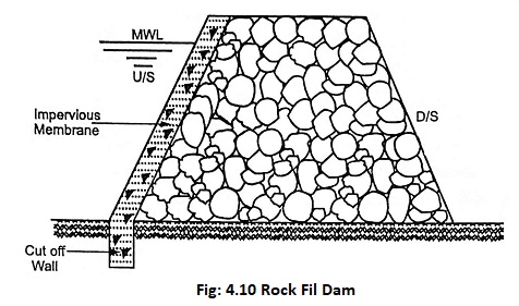
The impervious membrane is provided on the upstream side for water tightness. The different materials used for impervious membrane are: earth, concrete, steel and asphalt. A cut off wall is provided to prevent seepage under the dam. These dams are suitable for moderate heights.
Trash rack
The main purpose of trash rack is to prevent the entry of debris which might damage the turbine runners or choke-up nozzle of impulse turbine. If the winter season is severely cold, then the trash rack is heated electrically to prevent ice from clinging to it or manual is used for removing debris from trash rack.
Trash rack is made of steel bars which is placed at the inlet to avoid debris from going into the intake. The spacing of trash plays a vital role in trash rack.
The spacing of trash depends upon the following factor.
- Type of turbine
- Size of floating material. The height of the trash rack will be changed depending upon the size of the floating material.
- Velocity of flow through trash rack
Velocity greater than 90 m/sec may cause trash rack system to vibrate. So it is necessary to maintain the bars to be rigidly sniffed and supported and also the velocity of flow (v) through trash rack should be kept within the limits so that it does not cause any great loss in head. It can be calculated by formula
![]()
where
- h = difference in head
- g = gravity
Surge tank
When the gates admitting water to the turbines are suddenly closed due to the action of governor, there is a sudden increase of pressure in the penstock due to the sudden decrease of flow of water in turbine. This sudden rise of pressure in the “penstock” is known as “water hammer“.
When the turbine gates are opened suddenly, to increase the load demands the turbine needs lots of water, hence the water rush through penstock and there is a tendency to cause vacuum in the system. So the penstock must withstand the positive hammer (or) pressure due to the closing of turbine gates and no vacuum should be produced in the system when the gates are closed due to increase in load condition.
So a surge tank is introduced between sluice gate and the fore bay nearest to the power house and the surge tank should be placed on a high ground to reduce the height of the tower, so that we can provide better regulation of water pressure in the system.
When the turbine gates are partially closed, the flow of water in turbine is reduced suddenly due the this water level starts rises in the surge tank. This produces a head of water in the surge tank and reduces the velocity of water in penstock. Due to the reduction in velocity of water in penstock to meet the demand of the turbine, the level of water in surge tank starts falling and fluctuate up and down till the friction is damped out.
When there is a sudden rise in load on the turbine, additional water is supplied from surge tank, which lowers the level of water in the surge tank and produces a accelerating head. This head increases flow of water in penstock. Due to this load demand is achieved, the water surface in the tank ceases to fall. Hence surge tank helps to maintain velocity and pressure in penstock and reduces the water hammer effect.
Fore bay
Another Components of Hydroelectric Power Plant is the fore bay which serves as a regulating reservoir by temporarily storing water when the load demand on the plant is reduced and also provides load increment by initial increment of water, while water in the canal is being accelerated. In many plants, the canal may be large enough to absorb flow vibrations. In some cases, the canal is long and its ends are enlarged to provide necessary temporary storage. If short forebay is provided as natural provided surge tank which absorbs flow vibrations as it does the work of surge tank. Some type of outlet structure is always provided in fore bay to direct water to the penstock depending upon local conditions.
Penstock
The pipe between sluice gate and prime mover (Turbine – which converts the kinetic energy of water in to mechanical energy to produce electric current) is called penstock.
The structural design of the penstock is same as for any another type of pipe but pipes used for penstock have to withstand very high pressure on inside surface during decrease in load conditions and also to withstand onside pressure during increased load conditions.
The pipes used for penstock are most commonly made of steel through reinforced concrete. If the distance between forebay and power house is short, then separate penstocks are equipped for each turbine. Penstocks are provided with head gates at inlet for repair and servicing of penstock and also an air inlet valve stem is provided at the inlet to prevent collapse of head gate during immediate closure of valve. A sufficient depth must be provided above penstock entrance in the surge tank to avoid formation of vortices (A whirlwind (or) whirlpool). This vortices carries air into penstock which leads lower turbine efficiency.
In cold weather conditions, it is advised to bury the penstock to avoid formation of ice and also to reduce the number of expansion joints.
Spillway
Spillway is like a safety valve of the dam. It discharges major flood without damaging the dam. At the same time, it keeps the reservoir level below the maximum level allowed.
Power house
A power house is divided into two sections.
- Substructure to support hydraulic and electrical equipment.
- Superstructure to house and protect the equipement.
It is necessary to determine the elevation of turbine with respect to tail water level to avoid cavitation.
In most of the power houses, all the operating equipment of the super structure are housed inside a building. Mostly the generator and exciters [The electronic oscillator that generates the carrier signal for a transmitter]. The turbines rotating on a horizontal axis are placed on the ground floor along the side of generator. The turbines rotating on vertical axis are just placed below the floor level.
If there is no convenient site for conventional type power house, it is always advantageous to locate power house under ground, under certain graphical conditions [a detailed graphic representation of the surface features of a place]. For example. Koyna power house in India which is a under-ground power house.
Draft tube
In reaction turbine installing, another essential Components of Hydroelectric Power Plant is the draft tube is the essential part which supplements the action of runner and utilises the remaining kinetic energy of water leaving turbine.
The draft tube is a divergent outlet passage connected to the tail race from the runner. The remaining kinetic energy of water coming out of runner is efficiently regained by decelerating the flow with a minimum loss in the draft tube by converting the flow into suction head. Thus the kinetic energy of water coming out from reaction turbine is regained which is the primary purpose of draft tube.
The secondary purpose of a draft tube is to place turbine located above tail race level. So the vertical distance of turbine runner above the water level in the tail race is well within an atmospheric head and outlet of draft tube. Draft tube should be sufficiently submerged in water with assured water seal makes the negative static draft head on the runner and also the positive head from the head water level is added to make up a total static head on turbine.