Interlocking Components in Electrical Drives:
Sensing of signals required for speed and current control loops. Sequencing and interlocking operations are explained in the previous section, whereas this section discusses components used in interlocking and sequencing operations, and protection. It should be noted that signals for Interlocking Components in Electrical Drives and sequencing operations must be obtained from potential free contacts.
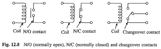
Relays: Both electromagnetic and solid state (electronic) relays are used. Electromagnetic relay coils have typical ratings of 12 V, 24 V, 48 V dc and output contact ratings up to 240 V, 5 A typically. Relays could have up to 4 N/O (normally open), 4 NC (normally closed) and 4 change over contacts. The N/O, N/C and changeover contacts are shown in Fig. 12.8.
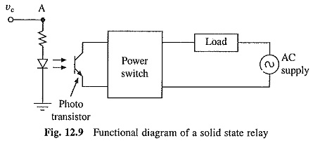
In a solid state relay, the relay function is achieved by means of electronic Interlocking Components in Electrical Drives. It also has isolated input and output, but no moving contacts. Functional diagram of solid state relay in shown in Fig. 12.9. When control signal is applied across terminal A, LED is turned on. Light from LED turns on a switch, usually a phototransistor or light activated SCR. With the help of zero voltage switch, relay turns on and applies power to the load at the instant of zero crossing of the source voltage. When control signal is removed, power to the load is disconnected when the load current passes through zero. Turn on and off of power to the load at zero current reduces the generation of electromagnetic interference (EMI), which is a problem with electromagnetic relays. Solid state relay has several other advantages over electromagnetic relay due to absence of moving parts such as longer life, maintenance free operation, and resistance to shock and vibration. The electromagnetic relays also have several advantages over solid state relays, such as multiple contacts (several normally open, normally closed and change over contacts possible) and ability to withstand such surges as those encountered in motor starting and braking and resistance to triggering by transient voltages.
Contactors: A relay is employed in control circuits, therefore, its contacts are designed to close and open low voltage and low current circuits. The contactor is a high power relay which has heavy duty contacts, designed to close and break power circuits. Typical ratings of the contactors are:
Low current contactors for Interlocking Components in Electrical Drives and sequencing: Coil voltage 240 V, output contact ratings 240 V, 40 A.
Power contactors: Coil voltage 240 V, output contact ratings 660 V, 880 A and auxiliary contact ratings up to 10 A.
Bar mounted contactors: Coil voltage 240 V, output contact ratings 1000 V, 1200 A and auxiliary contact rating up to 10 A.
Auxiliary Contacts: Contactors and circuit breakers usually have few auxiliary contacts (up to a maximum 4 N/O and 4 N/C), in addition to the main (or power) contact. Auxiliary contacts are low current, low voltage contacts similar to relays (generally rated up to 240 V, 5 A), and are mainly employed to sense the state of breaker or contactor.
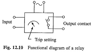
Direct voltage and direct current relays: These are solid state (electronic) relays used for monitoring over voltage and current. Input voltage signal is derived from voltage dividing network or current carrying shunt. Trip setting is done based on desired levels. When input signal exceeds the trip setting, output contact changes its state from open to close or vice versa. The output contacts are potential free. These are available as 2 N/O and 2 N/C or change over or suitable combinations of these. Ratings are available up to 240 V, 5 A. A schematic diagram of a relay is shown in Fig. 12.10.
Microswitch: Usually two to three changeover contacts are provided (rating up to 240 V, 5 A) for microswitches. When the fuse blows, inside lever of microswitch operates and the contacts change from N/O to N/C or vice versa. A trip indication is normally available as blown out pip.
Airflow switch: These are mechanical devices working on the same principle as a microswitch. However, the lever here is operated by airflow within a certain velocity band (say 4.5-5.5 m/s). Usually they have one changeover contact (rating up to 240 V, 5 A) and are used for monitoring air velocity when cooling fans are used to cool the converter stack.
Temperature sensors: These are generally bimetallic thermal strips. Differential expansion of strips causes opening of a contact (rating 240 V, 5 A) at a set temperature. These are used for monitoring the temperature of heat sinks carrying power devices. Temperature setting range covered is from 60 to 110°C. Output signal is used to protect the devices against over temperatures.
Cooling fan: Power converter rating can be improved by using a fair for forced air cooling of the converter stack: Air velocities up to 7 m/s (measured at cooling fins of heat sinks) are used. Fans used range from 75 to 800 W, depending on the size of converter stack. An airflow switch is employed to sense air velocity at heat sinks. Switch changes its contact position when it senses the desired velocity. This is used to obtain interlock signal for the drive to start.
Sometimes bimetallic temperature sensor is used as a substitute to the airflow switch. Sensor monitors the heat sink temperature which when crosses a set limit, drive can be either stopped or drive current limit reduced. Normally used trip settings range from 75 to 100°C.
Timers: If a particular drive requirement is to be met in a given time, a timer is used in the control logic. Timer can be pneumatic, electromechanical or electronic. Time delay relays are examples of timers and their setting is done based on the need. Its output contacts change from N/O to N/C or vice versa when the time setting is exceeded. Output contacts are available in suitable combinations such as 2 N/O and 2 N/C or 4 changeover. Ratings are 240 V, 5 A.
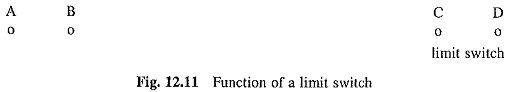
Limit switches: A limit switch brings out a change in the drive operation after a moving part reaches a given position. Function of a limit switch can be understood by the example of the ingot buggy control of a blooming mill. Function of the ingot buggy is to transport hot steel piece known as ingot from soaking pits to rolling stand. After the ingot is loaded on buggy at position A (Fig. 12.11), the buggy is accelerated to full speed by a drive mounted on it. From position B to C the buggy runs at a constant speed. When the buggy reaches position C, the operation of drive is shifted from motoring to braking, and buggy is brought to a stop. Since dynamics of the buggy is known, position C is so chosen that the buggy stops at position D which is just in front of rolling stand. The changeover of operation from motoring to braking at position C is done with the help of a limit switch. When position C is reached, contact of limit switch closes and initiates control logic of drive to change the operation from motoring to braking.
Limit switch can be of mechanical type or a photoswitch. In mechanical limit switch a projection on the buggy makes contact with the lever of limit switch mounted at position C. A photoswitch consists of a light sensor and a relay. A light source is mounted on buggy. When the buggy reaches position C the light from its light source strikes the sensor, the relay is energised, closing or opening one or more sets of relay contacts. The photoswitches are generally preferred because due to absence of moving parts, they hardly required any maintenance and have long life.
Overcurrent protection: Function of the overcurrent protective device is to protect the motor, power modulator and other devices in the power circuit from short circuits and grounds. The two devices commonly employed are circuit breaker and fuse. Both these devices should be capable of carrying motor currents during normal transient operations such as starting, braking and reversing without disconnecting motor from the line. For a motor fed from power modulator (or converter), these devices are set to match the transient rating of power modulator or the motor, whichever has lower value.
When motor is fed directly, overcurrent setting is made between 250 and 400% of full load. Overcurrent protection not only provides overcurrent protection, but also disconnects motor from the source. The circuit breaker accomplishes both functions: When fuses are employed for overcurrent protection, a switch for disconnecting motor from the supply is also provided.
Overload Protection: Overload conditions in a motor may occur due to torque overloads, under voltage, unbalanced voltage and single phasing. Maximum overload occurs when the rotor (or armature) of a motor is stalled when running normally, a condition referred to as locked rotor condition. When overloading occurs, higher than permissible current flows in one or more phases causing temperature in a certain part of motor to exceed the safe value. Too high increase of temperature beyond safe limit can damage the winding insulation and motor’s lubricating fluids immediately. Damage to insulation of winding leads to short circuit and burning of the winding. Small increase of temperature beyond safe limit may not damage winding immediately, but it progressively deteriorates the quality of insulation and thus initiates the process of its failure at a later date.
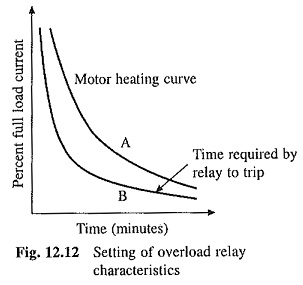
Winding loss is proportional to the square of the current. Therefore, higher the overload, lesser the time taken by winding temperature to cross the safe limit. Curve A of Fig. 12.12 shows the nature of relationship between percentage full load current and time in minutes taken by the temperature to exceed safe limit. Overload relay, which is used to protect the motor against overloads, should have a matching relationship between current overload and time required to trip and should lie below curve A. This relationship is shown by curve B.
There are two types of overload relays, viz. thermal and magnetic. Bimetallic thermal overload relays which are commonly used have a heating coil which carries the motor winding current. Heat produced by heating coil heats up bimetallic strip. The unequal expansion of two metals makes the strip to bend. Strip pushes against the breaker contacts, causing the contacts to open. The magnetic overload relay has a movable core inside a coil through which the motor current flows. Normal motor current is not enough to cause core to move. When overload occurs, the core moves’. The movement is opposed and damped by a thick viscouse liquid or dashpot. The relay trips after certain time depending on the overload (curve B).
When a motor is fed from power modulator, the overload protection, in addition to the motor, also protects power modulator against the overloads. Care should be taken to ensure that the overload relay characteristic B (between current overload and time required to trip) lies below the percentage full load current vs time (time required to exceed safe limit) characteristics of both—power modulator and motor. In closed loop systems, overload relay is not required because the overload protection is generally provided by current limit control or inner current loop.
It may be noted that overload protection is different from overcurrent protection. The former is used for protection against sustained overloads whereas latter is employed to protect against faults such as short circuit.
Ground fault protection: Large and expensive motors are usually provided with ground fault protection. Ground fault occurs when a current carrying conductor accidentally touches a grounded conducting material. Depending on the material resistance, the current may be small or large. A large current will usually blow a fuse or trip a circuit breaker whereas small current may not be enough to do so. Because of high resistance between conducting material and the ground, potential of the conducting material can be large enough to kill or injure humans. The fault current, if allowed to flow for large periods, can cause fire.
The ground fault relay works on the principle that in an ac motor, the sum of three-phase current during fault will not be zero, and in a dc motor the sum of currents of incoming and outgoing leads will not be zero.
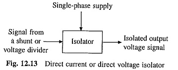
Direct current and direct voltage isolators (or sensors): In some drives, current feedback is obtained from dc output current of converter and voltage feedback from voltage divider network connected across dc output terminals of the converter. Under such situations, current and voltage feedback signals before feeding in the control electronics are isolated as the power circuit works at considerably higher voltages compared to control electronics. Isolators working on modulation and demodulation principle, as explained in Chapter 3, are now commercially available. Typical isolators are shown in Fig. 12.13. Isolators have three port galvanic isolation and isolation levels are maintained at 2.5 kV for power circuit voltages up to 415 V. Depending upon the current or voltage signal to be isolated, these are called ‘Direct Current’ or ‘Direct Voltage’ Isolators. Output signal of these isolators is a voltage signal usually in the range of ± 10 V.