Components of Protection System:
Some of the more commonly used Components of Protection System are
-
Relays
-
Circuit Breakers
-
Tripping and Other Auxiliary Supplies
-
Current Transformer (CT)
-
Voltage Transformers (VT)
-
Linear Coupler
Relays:
The main function of a protective relay is to isolate a faulty section with the least interruption to service by controlling the circuit breaker, when abnormal conditions develop. Thus the relays may be designed to detect and to measure abnormal conditions and close the contacts in the tripping circuit.
The following two categories of relays are most commonly used in protective relaying:
- Secondary indirect-acting relays: a group including practically all kinds of relays, e.g. current, voltage, power, impedance, reactance and frequency, whether minimum or maximum.
- Secondary direct-acting relays: a group of overcurrent and under-voltage relays designed to operate instantaneously or with time lag. These are primarily relays of the electromagnetic type which are built into circuit breaker operating mechanisms.
Circuit Breakers:
Circuit breakers of various types are installed in all power circuits to Open and close them under normal load conditions. Circuit breakers must correspond to nominal current and voltage rating and MVA breaking capacity to the load and fault power conditions at the given point of the circuit where they are incorporated. To isolate a fault from the power system one or more circuit breakers are required in conjunction with the protection.
Circuit breakers may be operated either manually or automatically. For our consideration here we will assume that it is controlled by a protective relay, so that when opening (tripping) is required a trip coil is energized, which releases energy stored in the mechanism thus causing the main contacts to part. The relay usually closes its contacts directly or via an auxiliary relay to close the trip coil circuit through a battery thus energizing the trip coil. When more than one breaker is to be tripped or where the trip coil current exceeds the relay-contact rating, an auxiliary relay of proper contact rating must be used.
While closing the trip coil circuit which is highly inductive the duty on the relay contacts is not so severe; but while breaking the trip coil current considerable damage would be done to these contacts. In order to overcome this difficulty an auxiliary switch operated by a mechanical link mechanism of the circuit breaker is connected in series with the trip coil and relay contacts. This auxiliary switch opens when the breaker contacts open. This action, however, takes place before the contacts of the relay open. This ensures that any inductance voltage would appear across the auxiliary contacts only and not across the relay contacts. The latter are thus saved from any possibility of burning.
The time of operation of circuit breaker actually depends on its design and usually lies between 0.05 and 0.25s. This must be accounted for while calculating final fault clearance time.
Tripping and Other Auxiliary Supplies:
It is quite evident that a source of power supply other than the supply circuit being protected is required for the operation of the relays and the circuit breakers. It also goes without saying that such an auxiliary supply should be the most reliable one. Protective relay and automatic control schemes, in power system practice use two kinds of auxiliary supply: d.c. or a.c.
D.C. auxiliary power supply is provided from storage batteries maintained continuously charged by some type of supply set or a charger. The advantages of storage batteries are their high reliability and independence of a.c. power circuit conditions and of the existence of faults. Usually the voltage of the auxiliary supply is maintained at 110 V. All possible means are exploited in designing the auxiliary supply circuits to make them most reliable, such as by dividing all the receivers of the auxiliary d.c. according to their responsibility into different categories. Of these the most important are the protective relays, automatic control and the circuit breaker tripping circuits. Use of sensationalized buses is frequently made for such supplies. Separate buses may also be provided for supplying power to relays, circuit breakers and other indicating circuits such as alarm or warning signals.
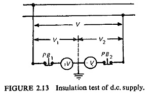
All d.c. auxiliary supply circuits must have their insulation resistance maintained at an adequate level, as any breakdown in the insulation with respect to earth may lead to false tripping due to formation of a path for bypass of the current round the control devices. Because of this danger every d.c. auxiliary supply installation must include a unit for constantly monitoring the condition of the insulation (insulation resistance to earth). A simple circuit providing such a test is shown in Fig. (2.13). When the insulation is healthy the voltage of each pole relative to earth V1 and V will be equal and half the voltage between both the poles. In case the insulation of one pole drops in value with respect to earth, the voltage to earth of this pole will also drop, but the voltage to earth of the other pole of the circuit will increase by the same amount.
Wherever conditions permit, it is of decided economic advantage to use a.c. instead of d.c. auxiliary supply for circuit breaker control and for energizing the protective relay. A.C. auxiliary supply for the protective relay scheme is mainly derived from the CTs. Under fault conditions, the current passing through the secondary of properly selected CTs, will always be sufficient to reliably trip the associated circuit breaker.
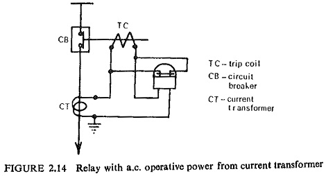
Figure (2.14) shows feeder overcurrent protection using a.c. auxiliary supply from CT. In this scheme the relay has normally-closed contacts. During normal operation the relay contacts continuously shunt the circuit-breaker trip coil and thus keep the breaker closed. As and when abnormal conditions are approached the relay operates to open its contacts. This puts the trip coil into CT circuit and the circuit-breaker trips. Many other schemes are also possible.
Current Transformer (CT):
The primary circuit currents which are of high-magnitudes are to be reduced to values suitable for relay operation with the help of current transformers (CTs). Thus the CTs essentially insulate the secondary (relay) circuits from the primary (power) circuits and, provide currents in the secondary which are proportional to those in the primary. The primary winding of the CT is connected in series with the load and carries the actual power system currents (normal or fault). The secondary is connected to the measuring circuit or the relay, which together with the winding impedance of the transformer and the lead resistance constitutes the burden of the transformer.
The CT is similar in operation to any other transformer so that the primary current consists of two Components of Protection System, viz. the secondary current which is transformed in the inverse ratio of the turns ratio and the exciting current which magnetizes the core. The latter current is not transformed and is the cause of the transformer errors. It is because of this reason that certain values of secondary currents could never be produced whatever the value of primary current, this happens when the core saturates and disproportionate amount of primary current is required to magnetize the core.
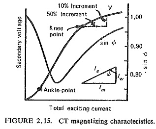
The general shape of a CT magnetization curve is shown in Fig. (2.15). The shape will change for different core materials. The characteristic is divided into three regions defined by the ankle point and the knee point. The boundary between the saturated and unsaturated regions is marked by the knee point which is defined as the point at which a 10% increase in secondary voltage produces a 50% increase in exciting current. The other characteristic curve shown in the diagram is the phase angle of exciting current which is not of much importance for protective CTs. It may, however, be noted that the working range of a protective CT extends over the full range between the ankle and the knee points and beyond, whereas the measuring CT usually operates in the region of the ankle point.
This is because of the radical difference in their basic functions. Measuring CTs require comparatively high accuracy over the range of 10% to 120% rated current, and it is an advantage if the CTs saturate for currents above this range in order to protect the instruments. Protection CTs, on the other hand, require linear characteristics up to the secondary voltage corresponding to maximum fault current flowing in the connected burden.
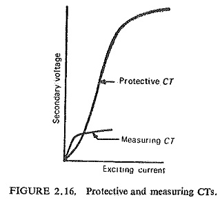
Figure (2.16) shows the characteristics of two CTs both for the same rated burden, but one for protection and the other for measurement. It is quite obvious that a core of larger cross section would be required for a protective CT if the material has to be the same. Grain oriented steels having high saturation levels are used as core materials for protective CTs and nickel-iron alloys having low exciting ampere-turns per unit length of the core are used for measuring CTs and the knee point ‘occurs at a relatively low flux density.
It is common practice to use IA secondary rating CTs. There is a practical limit to the number of turns which can be wound on the bar primary CT which is usually about 1500 secondary turns. When rated primary currents much in excess of 1500 A are encountered then the main bar primary CT with rated secondary current of 5A or 10A along with auxiliary CTs of 5/1 or 10/1 A respectively, are used.
Voltage Transformers (VT):
It is not possible to connect the voltage coils of the protective devices directly to the system in case of high voltage systems. It is therefore necessary to step down the voltage and also to insulate the protective equipment from the primary (power) circuit. This is achieved by using a voltage transformer (VT) also known as a potential transformer (PT) which is similar to a power transformer. The voltage transformer is rated in terms of the maximum burden (VA output) it delivers without exceeding specified limits of error, whereas the power transformer is rated by the secondary output it delivers without exceeding a specified temperature rise. The output of VTs is usually limited to a few hundred volt amperes and the secondary voltage is usually 110 V between phases.
Ideally a VT should produce a secondary voltage exactly proportional to the primary voltage and exactly in phase opposition. This cannot obviously be achieved in practice owing to the voltage drops in the primary and secondary coils due to the magnitude and power factor of the secondary burden. Thus, ratio errors and phase angle errors are introduced.
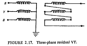
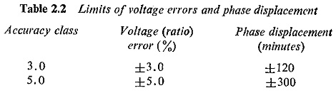
The limits of ratio and phase angle errors for VTs used for protection are much larger than those required for measurement purposes only. The acceptable limits of error for protective VTs as specified by IS:3156 (Part III)-1966 are shown in Table 2.2. A three-phase residually connected VT is shown in Fig. (2.17), where all the three phases of the primary windings are connected between line and earth and the secondary windings are connected in an open delta. In this case the residual voltage is equal to three times the zero sequence voltage. In order to have a voltage in the secondary circuit there must be zero sequence voltages in the primary circuit. Hence such an arrangement is used in neutral displacement schemes and for supplying the voltage circuit of directional earth fault relays.
There arc two types of voltage transforming devices: the conventional wound type voltage transformer and the capacitor voltage transformer. The wound type VT is conveniently used for system voltages up to or below 132 KV for economic reasons, and the capacitor VT is used for voltages above 132 KV. The capacitor VT is essentially a capacitance potential divider with the basic circuit shown in Fig. (2.18a). If the current flowing in the output circuit (i.e., in the connected burden) is negligible then

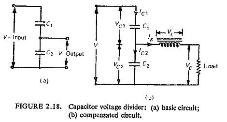
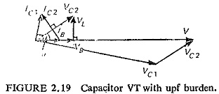
But when appreciable current flows in the burden, errors, both in ratio and phase, are introduced, because of the load current flowing through the capacitor C1. The voltage drop on load due to reactance of the capacitors can be compensated by inserting an inductive reactance in series with the Ioad as shown in Fig. (2.18b). The requirement is that a current flowing in the burden shall meet zero impedance in the capacitor divider. In other words, the circuit must offer zero impedance to the load current with the line and earth terminals short circuited, i.e., ωL = 1/(ωC1 + ωC2). Values of C1 and C2 are so chosen that a major part of the voltage drops across C1, i.e. C1≪C2 so that ωL ≈ 1/ωC2. The vector diagram of the compensated circuit for a unity power factor (upf) load is shown in Fig. (2.19). The following three conditions are of interest:
- For constant voltage V and a constant voltage VB a change in burden, i.e. IB changes Vc1, Vc2 and VL.
- For zero burden impedance, i.e. output terminals short circuited, the circuit has C1 in series with L and C2 in parallel forms an acceptor circuit tuned to the fundamental frequency. This results in increasing Vc1,Vc2,Ic1,Ic2 and IB to infinity. To protect from these conditions a protective spark gap is connected across C2.
- For infinite burden impedance or for output terminals open circuited VL is zero and VB = Vc2.
Linear Coupler:
An iron-cored CT has the limitation of saturation and owing to d.c, offset transient component present in the fault current, the stability on heavy through faults may be difficult to obtain.
With air-cored CTs, also known as linear couplers, the problem of saturation and d.c. offset transient are overcome. Two major difficulties with relay transient problems are differential saturation and the transference of d.c. through the iron-cored CT. These are obviously solved; firstly because iron has been removed, and secondly because this device transforms the exponential waveform with a high degree of attenuation of the d.c. offset in the output wave form.
Assuming the primary current ip to have 100% d.c. offset, i.e.
![]()
The secondary voltage is given by M di/dt,
![]()
It can thus be seen that the d.c. component voltage has been attenuated by a ratio R/X which may be 1/10 to 1/20 depending on the system.