Optical Encoders:
The Optical Encoders are used to get the information about the position, direction of rotation, and speed of rotation of various motor shafts. They provide this information in digital form which can easily be used by microcomputers to control the speed, direction of rotation and position of the motor shaft.
There are two basic types of Optical Encoders:
-
Absolute encoders and
-
Incremental encoders
1.Absolute Encoders:
Absolute encoder consists of a binary coded disk mounted on the motor shaft such that it rotates with the shaft. The Fig. 15.21 shows a typical binary coded disk. The disk has four tracks with some sections are transparent and some are opaque. The section shown with grey colour are opaque and section shown with white colour are transparent.
A LED is mounted on one side of each track, and a phototransistor is mounted on the other side of each track, opposite the LED. When the light from the LED through the transparent section reaches to the phototransistor, it conducts and produces output of logic 1. Opaque sections does not allow to pass light to the phototransistor and thus they switch off it to produce output of logic 0. The Fig. 15.21 shows the binary code produced by four phototransistors at various positions of motor shaft. Each code represents an absolute angular position of the shaft in its rotation.
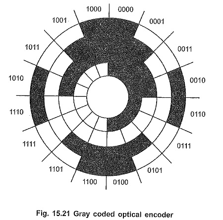
As shown in the Fig. 15.21, usually gray code is used rather than a normal binary code. The gray code reduces the size of the largest possible error in reading the shaft position to the value of the least significant bit.
Absolute encoding using a Gray code disk has the advantage that each position is represented by a specific code which can be directly read through the input port by the microcomputer. However, absolute encoding has a disadvantages that it needs multiple pairs of LEDs and phototransistors, and it is difficult to keep a track of position during multiple rotations.
2.Incremental Encoders:
The incremental encoders solve some problems of absolute encoders. They produce a pulse for each increment of shaft rotation. It has circular windows around the circular disk mounted on the motor shaft. This disk rotates with the shaft. One pair of LED and phototransistor is mounted such that LED is on the one side of the disk and phototransistor is on the other side of the disk.
During rotation when circular window come across the LED, the light passes to the phototransistor. As a result, phototransistor conducts and produce low output at its collector. Each time when light passes through window to the phototransistor, it conducts and output goes low, otherwise phototransistor is off and output is high. As disk rotates, the train of pulses are generated.
The number pulses in one rotation equals the number of circular windows on the disk. Therefore, by, counting number of pulses we can decide the position of the shaft as well as number of rotations performed by the shaft. By counting the number of rotations in specific time we can also calculate the speed of rotation.
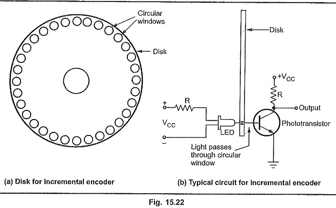
The disk shown in Fig. 15.22 has 32 circular windows. If after rotation. we have pulse count of 168, then we can say that the shaft has completed hill five rotations and one quarter rotation, because 168/32 = 5.25.