Photo Optical Modulator:
Photo Optical Modulator – The principle of an optical dc chopper is illustrated in Fig. 14.42. Devices of this type have been used widely in infrared signal detectors, whose output is a slowly varying dc product. The properties of the parallel connected photo resistor are such that the device produces a decrease in its internal resistance when struck by light.
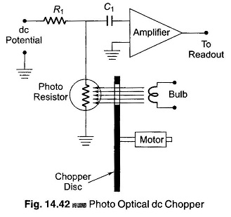
The photo resistor may have a dark resistance of several Meg-ohms, but has a dynamic resistance of 6 Ω or less when light falls on it. (In order to make use of this effect in a chopping system, a motor driven chopping disc supplied with a slit is rotated in front of the photo resistor.
The latter’s chopping frequency is determined by the number of the slots in the disc, and by the speed at which it is being rotated. A 1 slot disc, being rotated at 3600 rpm, would thus produce a chopping frequency of 60 Hz.
Two slots with rpm constant give 120 Hz; and with 10 slots the frequency would be 600 Hz.) The bulb may be driven by a simple relaxation oscillator in place of the motor.