Basic Principle of Chopper Circuit:
A Basic Principle of Chopper Circuit is essentially a thyristor switch in series with the load as shown in Fig. 11.27(a). A shunting diode is provided across the load for free-wheeling the load current when the thyristor is off. The thyristor shown enclosed by a dotted square can be turned-on and turned-off over a time period and the cycle is repeated.
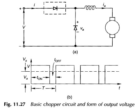
The flow of dc current through the chopper during the on-period necessitates the use of a forced commutation circuit for turning off the thyristor. The average value in the Principle of Chopper Circuit output voltage waveform shown in Fig. 11.27(b) is given by
where
- tON = on-time over one period
- tOFF = off-time over one period
- T = chopping period
![]()
It is therefore seen that the output voltage of a basic principle of Chopper Circuit is controlled by its duty cycle. It can be varied in the following ways:
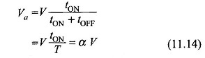
1. Constant-frequency System:
In this system f = 1/T (fixed), i.e. the chopping frequency or period are fixed and tON is varied to control α. This is pulse-width modulation. Figure 11.28 illustrates this system of control.
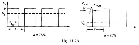
2. Variable-frequency System:
Here the chopping period T is varied and either tON or tOFF is held fixed as illustrated in Fig. 11.29. This is frequency modulation. This method of control presents two difficulties: (i) Control of Va requires variation of chopping frequency over a wide range. Filter design for variable-frequency operation is difficult. (ii) At low output voltage, a large value. of tOFF makes the motor current discontinuous.
Chopping frequencies as high as several hundred cycles/second are used in practice.
Step-up Chopper:
The chopper configuration of Fig. 11.27(a) produces an output voltage less than the input voltage. An output voltage higher than the input voltage can be obtained by the chopper configuration of Fig. 11.30. When the chopper is on, the inductor is in the source circuit and energy from the source is stored in it. When the chopper is turned off, the inductor current is forced to flow through the diode and load. Decreasing current causes the inductor voltage to reverse which now adds up to the source voltage such that the load voltage is higher than the source voltage (va > V). The energy stored in the inductor is released into the load.
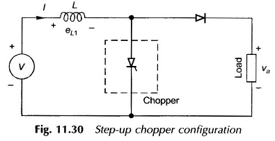
On the basis of average values, during the time the chopper is on, the energy stored in the inductor from the source is
![]()
During the time the chopper is off, the energy fed from the inductor to the load is
![]()
Assuming a lossless system, under steady-state the two energies will be equal, i.e
![]()
from which
For α varying between 0 to 1, the theoretical load voltage varies from V to ∞.
The step-up chopper can be employed for regenerative braking of a dc motor. In Fig. 11.30 if V represents the motor armature and Va the dc source, power is fed from the decreasing voltage motor to a higher but fixed voltage source.
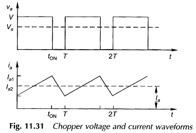
Voltage and Current Waveforms:
The voltage and current waveforms for the chopper configuration of Fig. 11.27(a) for a continuous current case are given in Fig. 11.31.
Chopper Commutation:
It has already been mentioned that the thyristor in a chopper has to be turned off by auxiliary commutation circuitry. The commutation can be broadly classified as:
1. Forced Commutation:
In this type of commutation, current through the thyristor is forced to become zero to turn it off. This can be accomplished in two ways.
- Voltage Commutation—A charged capacitor momentarily reverse-biases the conducting thyristor to turn it off.
- Current Commutation—A current pulse is forced in the reverse direction through the conducting thyristor. As the net current becomes zero, the thyristor is turned off.
2. Load Commutation:
The load current flowing through the thyristor either becomes zero (as in natural or line commutation employed in converters) or is transferred to another device from the conducting thyristor.