Generation of High Frequency AC High Voltage:
High Frequency AC High Voltage are required for rectifier d.c power supplies. Also, for testing electrical apparatus for switching surges, High Frequency AC High Voltage damped oscillations are needed which need high voltage high frequency transformers. The advantages of these high frequency transformers are:
- the absence of iron core in transformers and hence saving in cost and size,
- pure sine wave output,
- slow build-up of voltage over a few cycles and hence no damage due to switching surges, and
- uniform distribution of voltage across the winding coils due to subdivision of coil stack into a number of units.
The commonly used High Frequency AC High Voltage resonant transformer is the Tesla coil, which is a doubly tuned resonant circuit shown schematically in Fig. 6.13a. The primary voltage rating is 10 kV and the secondary may be rated to as high as 500 to 1000 kV. The primary is fed from a d.c. or a.c. supply through the capacitor C1. A spark gap G connected across the primary is triggered at the desired voltage V1 which induces a high self-excitation in the secondary. The primary and the secondary windings (L1 and L2) are wound on an insulated former with no core (air-cored) and are immersed in oil. The windings are tuned to a frequency of 10 to 100 kHz by means of the capacitors C1 and C2.
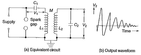
The primary coil is wound on an insulator fibre tube of about 1 m length to represent a cylindrical or helical winding and consists of a few tens of turns (usually copper strip or tubings). The secondary winding is spaced quite away from the primary winding on another concentric fibre or pyrex tube with a few thousand turns. The whole assembly will be immersed in an oil tank under pressure. With separate bushings taken out for the primary and the secondary windings, the primary winding is supplied through a high voltage capacitor rectifier unit rated for 10 kV to 50 kV or more and the power rating of the transformer may be 10 kVA or more.
The output voltage V2 is a function of the parameters L1,L2,C1,C2, and the mutual inductance M. Usually, the winding resistances will be small and contribute only for damping of the oscillations.
The analysis of the output waveform can be done in a simple manner neglecting the winding resistances. Let the capacitor C1 be charged to a voltage V1 when the spark gap is triggered. Let a current i1 flow through the primary winding L1 and produce a current i2 through L2 and C2.
The Laplace transformed equations for the above are,
where I1 and I2 are the Laplace transformed values of i1 and i2.
The output voltage V2 across the capacitor C2 is
where V2(s) is the Laplace transform of V2.
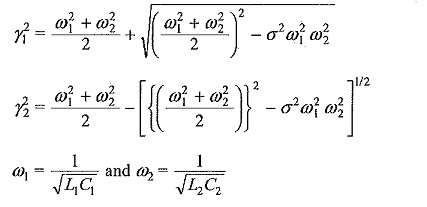
The solution for V2 from the above equations will be
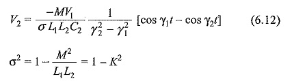
K= coefficient of coupling between the windings L1 and L2
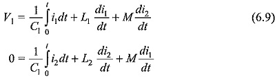
The output waveform is shown in Fig. 6.13b.
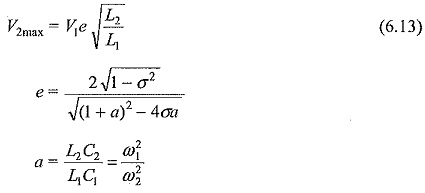
The peak amplitude of the secondary voltage V2 can be expressed as,
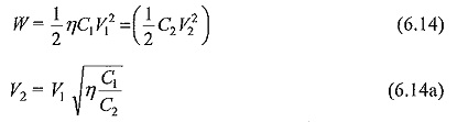
A more simplified analysis for the Tesla coil may be presented by considering that the energy stored in the primary circuit in the capacitance C1 is transferred to C2 via the magnetic coupling. If W1 is the energy stored in C1 and W2 is the energy transferred to C2 and if the efficiency of the transformer is η, then
It can be shown that if the coefficient of coupling K is large the oscillation High Frequency AC High Voltage is less, and for large values of the winding resistances and K, the waveform may become a unidirectional impulse. This is shown in the next sections while dealing with the generation of switching surges.