What is an Inductive Transducer?:
Inductive Transducer may be either of the self generating or the passive type. The self generating type utilizes the basic electrical generator principle, i.e. a motion between a conductor and magnetic field induces a voltage in the conductor (generator action). This relative motion between the field and the conductor is supplied by changes in the measured.
An inductive electromechanical transducer is a device that converts physical motion (position change) into a change in inductance.
Transducers of the variable inductance type work upon one of the following principles.
- Variation of self inductance
- Variation of mutual inductance
Inductive Transducers are mainly used for the measurement of displacement. The displacement to be measured is arranged to cause variation in any of three variables
- Number of turns
- Geometric configuration
- Permeability of the magnetic material or magnetic circuits
For example, let us consider the case of a general inductive transducer. The Inductive Transducer has N turns and a reluctance R. When a current i is passed through it, the flux is
![]()
Therefore
![]()
If the current varies very rapidly,
But emf induced in the coil is given by
![]()
Therefore
![]()
Also the self inductance is given by
Therefore, the output from an inductive transducer can be in the form of either a change in voltage or a change in inductance.
Change in Self Inductance with Numbers of Turns:
The output may be caused by a change in the number of turns. Figures 13.14(a) and (b) are transducers used for, the measurement of displacement of linear and angular movement respectively.
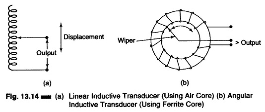
Figure 13.14(a) is an air cored transducer for measurement of linear displacement.
Figure 13.14(b) is an iron cored coil used for the measurement of angular displacement.
In both cases, as the number of turns are changed, the self inductance and the output also changes.
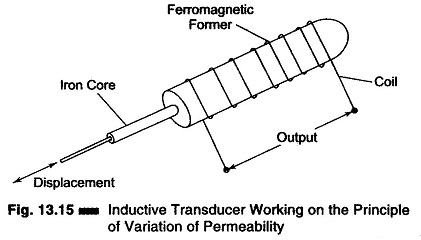
Transducer Working on the Principle of Change in Self Inductance with Change in Permeability:
Figure 13.15 shows an Inductive Transducer which works on the principle of the variation of permeability causing a change in self inductance. The iron core is surrounded by a winding. If the iron core is inside the winding, its permeability is increased, and so is the inductance. When the iron core is moved out of the winding, the permeability decreases, resulting in a reduction of the self inductance of the coil. This transducer can be used for measuring displacement.
Variable Reluctance Type Transducer:
A transducer of the variable type consists of a coil wound on a ferromagnetic core. The displacement which is to be measured is applied to a ferromagnetic target. The target does not have any physical contact with the core on which it is mounted. The core and the target are separated by an air gap, as shown in Fig. 13.16(a)
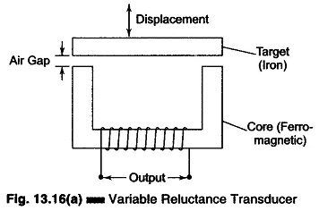
The reluctance of the magnetic path is determined by the size of the air gap. The inductance of the coil depends upon the reluctance of the magnetic circuits.
The self inductance of the coil is given by
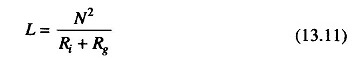
where
- N = number of turns
- Ri = reluctance of iron parts
- Rg = reluctance of air gap
The reluctance of the iron part is negligible compared to that of the air gap.
Therefore
![]()
But reluctance of the air gap is given by
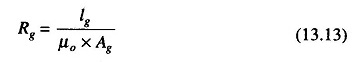
where
- lg = length of the air gap
- Ag = area of the flux path through air
- μo = permeability
Rg is proportional to lg, as μo and Ag are constants.
Hence L is proportional to 1/lg, i.e. the self inductance of the coil is inversely proportional to the length of the air gap.
When the target is near the core, the length is small and therefore the self inductance large. But when the target is away from the core the reluctance is large, resulting in a smaller self inductance value. Hence the inductance of the coil is a function of the distance of the target from the core, i.e. the length of the air gap.
Since it is the displacement which changes the length of the air gap, the self inductance is a function of displacement, albeit a non-linear one.
A variable reluctance bridge is shown in Fig. 13.16(b).
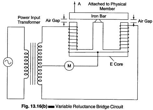
A separate coil is wound on each outside leg of an E core and an iron bar is pivoted on the centre leg. A magnet extends from each outside leg through an air gap and through the iron bar to the centre leg.
The moving member is attached to one end of the iron bar and causes the bar to wobble back and forth, thereby varying the size of each air gap.
The bridge consists of two transducer coils and a tapped secondary of the input power transformers. It is balanced only when the inductance of the two transducer coils are equal, i.e. when the iron bar is in a nearly exact horizontal position and the air gaps are equal.
Whenever the iron bar at point A moves and alters the air gap, the bridge becomes unbalanced by an amount proportional to the change in inductance, which in turn is proportional to the displacement of the moving member.
The increase and decrease of the inductance with varying air gap sizes is non-linear, and so is the output. Also, the flux density within the air gaps is easily affected by external fields.