Capacitive Pressure Transducer Working Principle:
Capacitive Pressure Transducer Working Principle – A linear change in capacitance with changes in the physical position of the moving element may be used to provide an electrical indication of the element’s position.
The capacitance is given by
![]()
where
- K = the dielectric constant
- A = the total area of the capacitor surfaces
- d = distance between two capacitive surfaces
- C = the resultant capacitance.
From this equation, it is seen that capacitance increases (i) if the effective area of the plate is increased, and (ii) if the material has a high dielectric con-stmt.
The capacitance is reduced if the spacing between the plates is increased. Transducers which make use of these three methods of varying capacitance have been developed.
With proper calibration, each type yields a high degree of accuracy. Stray magnetic and capacitive effects may cause errors in the measurement produced, which can be avoided by proper shielding. Some capacitive dielectrics are temperature sensitive, so temperature variations should be minimized for accurate measurements.
A variable plate area transducer is made up of a fixed plate called Stator and a movable plate called the Rotor.
The rotor is mechanically coupled to the member under test. As the member moves, the rotor changes its position relative to the stator, thereby changing the effective area between the plates. A transducer of this type is shown in Fig. 13.28.
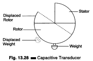
Such a device is used to detect the amount of roll in an aircraft. As the aircraft rolls to the left, the plates moves to the relative position shown by dashed lines in Fig. 13.28 and the capacitance decreases by an amount proportional to the degree of roll. Similarly to the right. In this case the stator, securely attached to the aircraft, is the moving element. The weight on the rotor keeps its position fixed with reference to the surface of the earth, but the relative position of the plates changes and this is the factor that determines the capacitance of the unit.
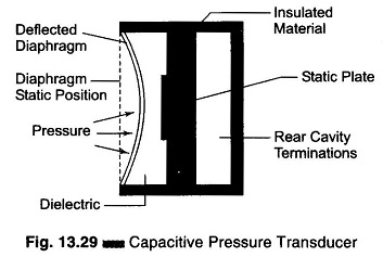
Figure 13.29 shows a transducer that makes use of the variation in capacitance resulting from a change in spacing between the plates. This particular transducer is designed to measure pressure (in vacuum).
Enclosed in an airtight container is a metallic diaphragm which moves to the left when pressure is applied to the chamber and to the right when vacuum is applied. This diaphragm is used as one plate of a variable capacitor. Its distance from the stationary plate to its left, as determined by the pressure applied to the unit, determines the capacitance between the two plates. The monitor indicates the pressure equivalent of the unit’s capacitance by measuring the capacitor’s reactance to the ac source voltage.
(The portion of the chamber to the left of the moving plate is isolated from the side into which the pressurized gas or vapour is introduced. Hence, the dielectric constant of the unit does not change for different types of pressurized gas or vapour. The capacity is purely a function of the diaphragm position.) This device is not linear.
Changes in pressure may be easily detected by the variation of capacity between a fixed plate and another plate free to move as the pressure changes. The resulting variation follows the basic capacity formula.
![]()
where
- A = area of one side of one plate in cm2
- n= number of plates
- t = thickness of dielectric in cm
- K= dielectric constant
The capacitive pressure transducer working principle, as in the capacitive microphone, is simple to construct and inexpensive to produce. It is particularly effective for HF variations.
However, when the varying capacitance is made part of an ac bridge to produce an ac output signal, the conditions for resistive and reactive balance generally require much care to be taken against unwanted signal pickup in the high impedance circuit, and also compensation for temperature changes. As a result, the receiving instrument for the capacitive sensor usually calls for more advanced and complex design than is needed for other transducers.