Torque in Round Rotor Synchronous Machine:
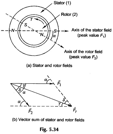
Torque in Round Rotor Synchronous Machine – When the stator and rotor windings of a machine both carry currents, they produce their own magnetic fields along their respective axes which are sinusoidally distributed along the air-gap. Torque results from the tendency of these two fields to align themselves. The flux components set up by the stator and rotor currents cross the air-gap twice and complete their circuits via the stator and rotor iron. These components fields cause the appearance of north and south poles on stator and rotor surfaces; the field axes being along north-south and out of the north pole. This is illustrated in Fig. 5.34(a) for a 2-pole structure.
The torque tending to align the two fields is produced only if the two fields have the same number of poles and are stationary with respect to each other. Two relatively rotating fields will produce alternating torque as they cross each other so that the average torque is zero. All varieties of electric machines (synchronous, induction and dc) are therefore devised to produce interacting fields with zero relative velocity.
Certain underlying assumptions are made at this stage of Round Rotor Synchronous Machine:
- Stator and rotor mmf s are sinusoidal space waves; this is sufficiently ensured by distributed windings.
- Rotor is cylindrical (nonsalient pole) so that the air-gap is uniform throughout.
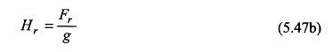
- The air-gap is narrow so that flux established in it is radial (negligible tangential component) and further the flux density does not vary significantly along a radial path in the gap. As a result, the field intensity H along any radial path is constant in the air-gap. The mmf across the air-gap at any space point is
 where g is the radial air-gap length.
- Reluctance of the iron path of flux is assumed negligible. As a consequence of assumptions 1-3, a sinusoidal space mmf wave produces a sinusoidal flux density wave in space in phase with it.
- Most of the resultant flux is common to both stator and rotor windings, i.e. it is mutual flux. The leakage flux linking either winding produces the leakage inductance as in a transformer. These affect only the net voltages applied to the ideal machine.
Let F1 and F2 be the peak values of the spatial sinusoidal mmf waves of the stator and rotor respectively as shown in Fig. 5.34(a) for a 2-pole machine; the angle between their respective positive peaks being denoted by α. As stated earlier, these mmf s can be represented as space vectors with magnitudes corresponding to their peak values and angles corresponding to their positive peaks. The resultant space mmf (which will also be sinusoidal being the sum of sinusoids) can be obtained by the vector summation as shown in Fig. 5.34(b). Using trigonometric relations, it easily follows that the peak value of the resultant mmf is
![]()
Since the reluctance of the iron path is negligible, the peak value of the resultant field intensity is
From Eq. (4.18) it is known that the coenergy density is
![]()
The average value of the coenergy density over the air-gap volume is
![]()
For a sinusoidal distribution,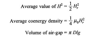
where D is the mean diameter at air-gap and l = rotor length = stator length The total coenergy of the field is then
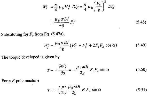
From the torque expression of Eq. (5.51) it is seen that the torque developed is proportional to the peak values of the stator and rotor mmfs and is proportional to the sine of the angle between the axes of the two fields. The negative sign in Eq. (5.50) indicates that the torque acts in a direction to reduce α, i.e. to align the two fields. Obviously, equal and opposite torques will act on the stator and rotor.
With reference to the geometry of Fig. 5.34(b) it is found that
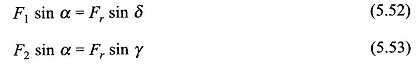
The torque expression of Eq. (5.51) can therefore be expressed in two more alternative forms,
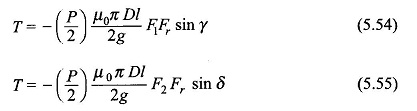
The Torque in Round Rotor Synchronous Machine in the expressions of Eqs (5.54) and (5.55) can be immediately imagined to be the result of the interaction of the stator and the resultant mmf’s or the rotor and the resultant mmf’s and is proportional to the sine of the angle between the interacting mmf s. The expression of Eq. (5.55) is generally preferred in simplified machine models.
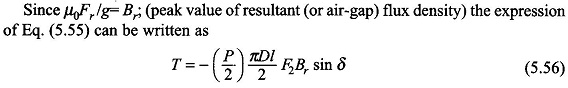
This expression reveals a design viewpoint; the torque of electromagnetic origin is limited by the saturation value of flux density (Br) in the magnetic material and maximum permissible mmf (F2). The maximum value of F2 is dictated by the maximum allowable winding current without exceeding the specified temperature rise.
An alternative and more useful form of the torque expression is in terms of the resultant flux/pole, Φr, rather than the peak flux density Br. Now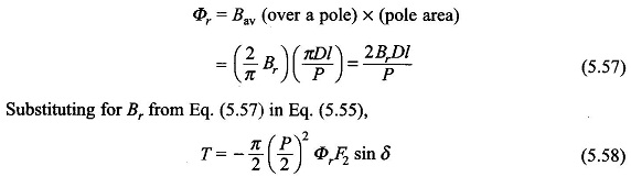
where Φr = resultant (i.e. air-gap) flux/pole due to superimposition of the stator and rotor mmf’s
Equation (5.57) can be written as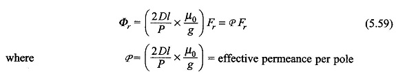
The effective permanence/pole relates the peak value of sinusoidal mmf wave and the flux/pole created by it. It is a constant quantity so long as the permeability of iron is assumed infinite, otherwise it is a function of Fr (i.e. P(Fr)) which decreases as Fr increases due to saturation of iron.