Construction of Cylindrical Rotor Synchronous Machine:
As stated earlier the Cylindrical Rotor Synchronous Machine offers constant permeance to mmf waves irrespective of the mechanical position of the rotor and is, therefore, simpler to model. Figure 8.1 shows the cross-sectional view of a 2-pole Cylindrical Rotor Synchronous Machine.
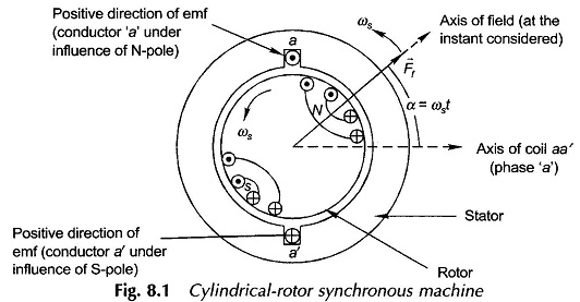
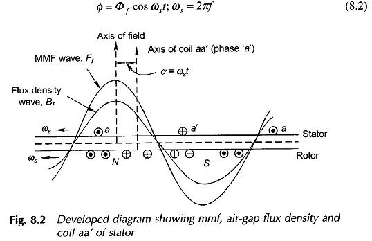
The rotor has distributed windings which produce an approximately sinusoidally distributed mmf wave in space rotating at synchronous speed ωs rad (elect.)/s (ns rpm) along with the rotor. This mmf wave is represented by the space vector Ff in the diagram and which at the instant shown makes an angle α = ωst with the axis of coil aa’ on the stator (coil aa’ represents the phase a). The peak value of the vector Ff is Ff. As a consequence of the uniform air-gap, the mmf wave Ff produces sinusoidally distributed flux density wave Bf, in space phase with it. Figure 8.2 shows the developed diagram depicting the space phase relationship between Bf and Ef waves. As the rotor rotates (at synchronous speed ωs), the Bf wave causes sinusoidally varying flux Φ to link with the coil aa’. The maximum value of this flux linkage is Φf, the flux per pole. Considering the time reference when Ff lies along the axis of coil aa’, this is a cosinusoidal variation, i.e.
It is, therefore, seen from Cylindrical Rotor Synchronous Machine that the flux linking the coil aa’ is a sinusoidal time variation and can be represented as the time phasor Φf. It will be referred to as flux phasor.
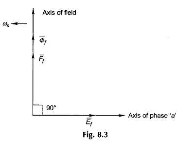
Consider now the space vector Ff as seen from the axis of coil aa’ on the stator. As Ff rotates at synchronous speed, it appears to be sinusoidally time-varying at ωs = 2πf elect. rad/s as is evident from the developed diagram of Fig. 8.2. Furthermore, when the maximum positive value of Ff space wave is directed along the axis of coil aa’, the flux linkage of the coil has maximum positive value. It may, therefore, be considered that the rotating space vector Ff as seen from the stator is a time phasor Ff which is in phase with the flux phasor Φf as shown in Fig. 8.3. The magnitude relationship between Φf and Ff will be governed by the magnetization curve; this will be linear if the iron is assumed to be infinitely permeable in which case
![]()
where P = permeance per pole.
The emf induced in the coil aa’ of N turns is given by Faraday’s law,
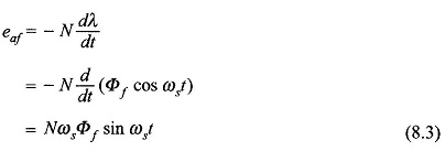
The positive direction of the emf is indicated on the coil aa’. This is also verified by the flux cutting rule when conductor a lies under the influence of N-pole of the rotor and conductor a’ simultaneously lies under the influence of the S-pole. It immediately follows from Eqs (8.2) and (8.3) that the emf eaf represented as time phasor Ef lags behind the mmf phasor Ff and the flux phasor Φf by 90° as shown in Fig. 8.3. This figure also shows the relative location of the field axis and the axis of phase a wherein the axis of phase a is 90° behind the rotor field axis. This is indicative of the fact that the field vector Ff lies 90° ahead of the axis of coil aa’ in Fig. 8.1 when the emf in coil aa’ has maximum positive value (projection of the phasor Ef on the axis of phase a). The rotor field axis is known as the direct-axis and the axis at 90° elect. from it is known as the quadrature-axis.
It immediately follows from Eq. (8.3) that the rms value of the emf induced in coil aa’ is
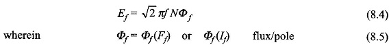
If being the direct current in the rotor field. Equation (8.5) between the flux/pole and field current is indeed the magnetization characteristic. Equation (8.4) suitably modified for a distributed (and also possibly short-pitched) stator winding is
![]()
It easily follows that the emfs produced in the other phases of the stator would progressively differ in time phase by 120°.
The conclusions drawn from the above discussion are indeed general and are reproduced below.
Whenever the magnetic structure of a Cylindrical Rotor Synchronous Machine is subjected to rotating mmf vector, it is seen as an mmf phasor from the stator with its flux phasor in phase with it, while the phasor representing the phase emf induced lags behind both these phasors by 90° (see Fig. 8.3).
It was shown in already that when a 3-phase stator supplies a balanced load, it sets up its own mmf vector Far (sinusoidally distributed in space), called the armature reaction, rotating at synchronous speed in the same direction as the rotor. The magnetic circuit is now subjected to two rotating mmf vectors Ff and Far, both rotating at synchronous speed with a certain angle between them. The objective here is to establish what determines this angle.
To begin with, it is observed from Cylindrical Rotor Synchronous Machine that in the generating operation of the machine, the emf and current have the same positive direction. Consider the case when the current Ia supplied by the coil aa’ is in phase with the coil emf Ef. It means that at the time instant when the emf is maximum positive in the coil aa’, its current also has maximum positive value. The emf in coil aa’ will be maximum positive when the field mmf vector Ff is 90° ahead of the coil axis (in the direction of rotation) as shown in Fig. 8.4(a). Simultaneously, Far is directed along the axis of coil aa’ which has maximum positive current at this instant. It is therefore, seen from Fig. 8.4(a) that Ff is 90° ahead of Far when Ef and Ia are in phase. The resultant mmf vector Fr is the vector sum
![]()
as shown in Fig. 8.4(a). It is observed that Fr lags Ff by angle δ. The corresponding phasor diagram, drawn as per the general conclusions stated earlier, is shown in Fig. 8.4 (b) wherein the phasor equation corresponding to the vector Eq. (8.7) is
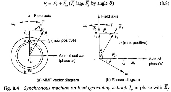
It is observed from the phasor diagram that la and Far are in phase; this is logical because Far is produced by la and is proportional to it. The resultant mmf vector Fr produces the resultant air-gap flux phasor Φr which in turn induces the emf Er in phase a lagging 90° behind the phasor Fr. The phase emf Er induced in the machine, called air-gap emf, lags by angle δ behind Ef (emf induced by Ff acting alone) which is the same angle by which Fr lags behind Ef in the vector diagram of Fig. 8.4(a) or the angle by which Fr lags behind Ff in the phasor diagram of Fig. 8.4(b). Ef is known as the excitation emf.
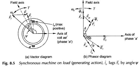
In case la lags Ef by an angle ψ, the positive current maximum in the coil aa’ will occur angle ψ later, so that Ff now lies (90° + ψ) ahead of Far as shown in the vector diagram of Fig. 8.5(a). The corresponding phasor diagram is shown in Fig. 8.5(b) wherein Ff leads Far by (90° + ψ). The phase angle between Er and Ia indicated by θ is the power factor angle provided it is assumed that the armature has zero resistance and leakage reactance so that the machine terminal voltage![]()
It is seen from Figs 8.5(a) and (b) that the field poles lie an angle δ ahead of the resultant mmf (or resultant flux) wave. The electromagnetic torque developed in the machine tries to align the field poles with the resultant field and is, therefore, in a direction as shown in Fig. 8.5(a) as well as in Fig. 8.5(b). It is immediately seen that the torque on the field poles is in opposite direction to that of rotation which means that mechanical power is absorbed by the machine. This is consistent with the assumed condition of the generating action (positive current in the direction of positive emf). It may, therefore, be concluded that in generating action, the field poles are driven ahead of the resultant flux wave by an angle δas a consequence of the forward acting torque of the prime mover. Also, the field poles are dragged behind by the resultant flux from which results the conversion of mechanical energy into electrical form.
As already shown, if the magnetic circuit is assumed linear, the magnitude of the torque is given by
![]()
where Φr is the resultant flux/pole, Ff the peak value of field ampere-turns and δ is the angle by which Ff leads Fr. It is also observed from Fig. 8.5(b) that Ef also leads Er by the same angle δ.
When Ff and Φr are held constant in magnitude, the machine meets the changing requirements of load torque by adjustment of the angle δ which is known as the torque (power) angle.
The torque expression of Eq. (8.9) can also be written in terms of voltages as
![]()
where
- Er = emf induced in the machine under loaded condition; called air-gap emf.
- Ef = emf induced by the field mmf Ff acting alone, i.e. the machine is on no-load with same Ff (or rotor field current) as on-load; called excitation emf.
The value of the constant K will be found in Sec. 8.8.
In motoring action of the Cylindrical Rotor Synchronous Machine, the positive current flows opposite to the induced emf. Since the phasor diagrams above have been drawn with the convention of generating current (i.e. current in the direction of emf), the armature reaction phasor Far will now be located by phase reversing the motoring current for consistency of convention. Accordingly the phasor diagram for motoring action is drawn in Fig. 8.6. It is immediately observed from this figure that Ff and Ef now lag Fr and Er respectively by angle δ. The torque of electromagnetic origin therefore acts on the field poles in the direction of rotation so that the mechanical power is output meaning thereby motoring action.
If the terminal voltage Vt = Er and its frequency is held constant by an external 3-phase source, called infinite bus, the machine operates as a generator (Fig. 8.5) or as a motor (Fig. 8.6) depending upon the mechanical conditions at a shaft.
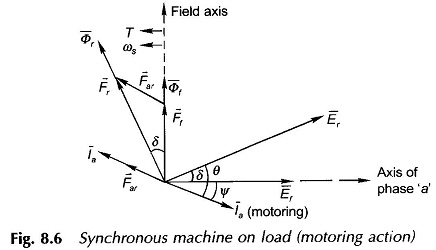
Figure 8.3 is representative of no-load conditions when the machine is said to be floating on busbars with zero stator current and the rotor being run at synchronous speed by external means (prime mover). If mechanical power from the prime mover is now increased, the field poles (rotor) move ahead causing current to be fed into the bus-bars. Under steady condition, the field poles lie ahead of the resultant flux wave by angle δ (Figs. 8.4 and 8.5) creating electromagnetic torque in opposition to the direction of rotor rotation; the value of δcorresponds to the balance of torques (or power, P = Tωs). The electrical power output is
![]()
which balances the mechanical power input from the primemover because there are no losses in the stator (resistance is assumed to be zero). Here Ia is the generating current taken to be positive in the direction of the machine’s induced emf Er.
If instead, the shaft is mechanically loaded from the no-load condition (Fig. 8.3), the field poles lag behind the resultant flux wave as in Fig. 8.6 creating electromagnetic torque in the direction of rotation thereby outputting mechanical power; the electrical input power being 3Vt(= Er)Ia cos θ, where Ia is the motoring current taken as positive in opposition to the positive direction of Er.
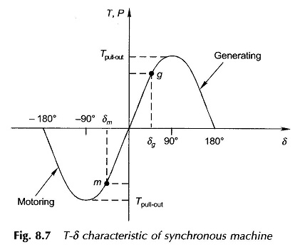
The torque (power)-angle (T-δ) relationship of Eq. (8.10) for fixed Ef and Er(=Vt) is drawn in Fig. 8.7 with δ taken as positive for generating action and negative for motoring action. The operating points as the generator and motor are indicated by g and m on this curve corresponding to the specific condition of loading. The characteristic exhibits, both in generating and motoring operation, a maximum torque at δ = 90°, called the pull-out torque, beyond which the Synchronous link between field poles and the resultant flux wave is severed and the machine falls out-of-step (or loses synchronism). The average developed machine torque now becomes zero and so the average electric power fed by the generating machine to the bus-bars, (infinite) or average electric power drawn by the motoring machine from the bus bars reduces to zero. The generating machine thus accelerates and so overspeeds (primemover power is assumed to remain constant) and the motoring machine decelerates and comes to stop.