Blocked Rotor Test of Induction Motor:
This Blocked Rotor Test of Induction Motor is used to determine the series parameters of the Circuit Model Parameters of an induction motor. The circuit is similar to that of a transformer short-circuit test. Short circuiting the load resistance in the circuit model of Fig. 9.8 corresponds to making s = 1 so that R2‘ (1/s – 1) = 0.
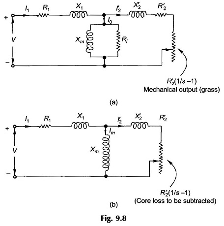
This means that the rotor must be stationary during this Blocked Rotor Test of Induction Motor, which requires that it be blocked mechanically from rotating while the stator is excited with appropriate reduced voltage. The Circuit Model Parameters seen under these conditions is given in Fig. 9.20(a).
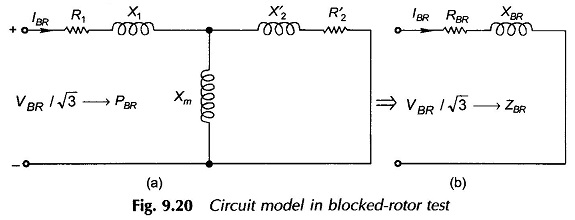
The current drawn by the motor in the Blocked Rotor Test of Induction Motor should be close to its rated value as the motor reactances are sensitive to saturation effects in the magnetic core. Rated current value is obtained by applying reduced voltage to the stator as blocked rotor presents short-circuited condition at the stator terminals (low impedance ZBR). The core loss at this reduced voltage can be ignored but as the magnetizing reactance (Xm) is much lower in an induction motor compared to a transformer, its effect cannot be ignored. This justifies the BR circuit model of Fig. 9.20 presented above.
In normal operating range of an induction motor the slip is low (2-8%). This means low rotor frequency and negligible rotor core loss. However, in Blocked Rotor Test of Induction Motor the rotor frequency is the same as the stator frequency which is much higher than rotor frequency in normal operation (it is almost negligible). Though with reduced voltage applied to stator the rotor core loss is small. The higher rotor frequency would affect the value of RBR and the rotor resistance as determined from the test, it will be smaller. (see the last para of this section). So for obtaining accurate results for rotor resistance, the BR test needs to be conducted at reduced frequency (25% of rated frequency). The reactances thus obtained are then scaled up to the rated frequency (50 Hz). However, for motors rated less than 25 kW, reduced frequency test is not warranted.
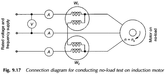
Metering and connection diagrams for the Blocked Rotor Test of Induction Motor are the same as in the connection diagram of Fig. 9.17. Of course the motor must be fed from appropriate low voltage (variable) source of frequency as discussed above.
The following readings are recorded during this test:
- VBR = stator voltage (line-to-line)
- IBR = stator current (average of three ammeter readings)
- PBR = power fed into stator; this mainly constitutes the copper loss in stator and rotor. At reduced voltage core loss (even in stator) is negligible.
From these test readings we can compute
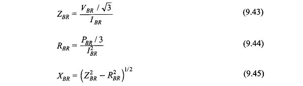
These values constitute the series equivalent of the BR test (Fig. 9.20(b)).
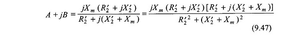
We, however, need to determine the Circuit Model Parameters R2‘, X1, X2‘, while R1 is known from the dc test. From the motor circuit in BR test as given in Fig. 9.20(b) we can write
![]()
![]()
Let
![]()
By making certain assumptions certain simplifications are carried out below:
As Xm ≫ R′22 , we can neglect R′22 in the denominator giving

But
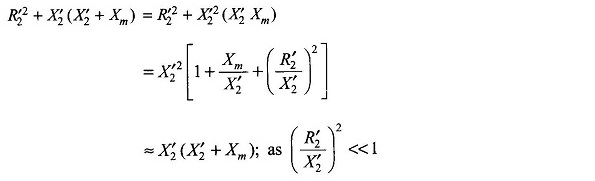
Then

Equation (9.46) then takes the form

The following results can then be written down with the knowledge that
![]()
Then
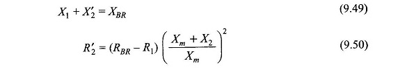
If (Xm + X2‘) > 10 R′2, which is usually the case, the approximations made in the Eq. (9.50) for R2‘ cause an error of less than 1%.
At this stage we need to separate out X1 and X2‘, which is not possible by the data of this (BR) test. Generally it is fairly accurate to assume that
![]()
If the Blocked Rotor Test of Induction Motor is conducted at rated frequency, two factors affect the value of R′2 as observed above. Firstly the rotor (winding) resistance increases as the frequency of rotor currents is the same as the rated frequency, while under normal operating conditions it is very small; few hertz or so. Secondly the frequency of rotor flux alterations is also at rated frequency. The rotor core then presents an effective resistance in parallel to R′2 thereby reducing effective R′2 as measured. These two effects tend to cancel each other out. So no reduced frequency testing is needed for small size motors (less than 25 kW).