No Load Test of Induction Motor:
In this No Load Test of Induction Motor, the motor is run on no-load at rated voltage and frequency. The applied voltage and current and power input to motor are measured by the metering as per Fig. 9.17.
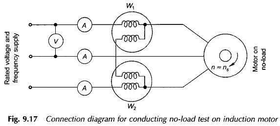
Let the meter readings be
- Power input = P0 (3-phase)
- Current =I0 (average of the three meter readings)
- Voltage = V0 (line-to-line rated voltage)
Power input at no-load (P0) provides losses only as the shaft output is zero. These losses comprise,
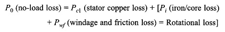
wherein core loss occurs only in the stator as the slip is extremely low (of the order of 0.001) and so the frequency of rotor current is as low as 0.05 Hz.
The magnitude of no-load current in an induction motor is about 30-40% of full-load current because of the air-gap. So the stator copper loss at no-load needs to be accounted for. This can be estimated by measuring dc stator resistance and correcting to ac value (50 Hz) and corrected for temperature (°C).
The mechanical power developed corresponds to Pwf only and so, as already mentioned above the slip is very low and the output resistance
![]()
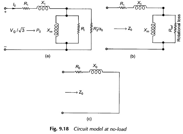
Also R2‘/s0 >> X′2 and so X′2 can be ignored. The corresponding no-load Circuit Model Parameters is drawn in Fig. 9.18(a) wherein R2‘/s0 appears in parallel to Ri. By combining the parallel shunt resistances, the final circuit at no-load is as given in Fig. 9.18 (b). Here Riwf accounts for rotational loss, i.e., core loss and windage and friction loss. Magnitude-wise Riwf >> Xm.
R1, the stator resistance, is found by dc testing of the stator winding and correcting the value to ac operation (at 50 Hz). X1, the stator leakage reactance, will be found from the blocked-rotor test which follows. We can then find Xm and Riwf from the No Load Test of Induction Motor data. By simplification of the circuit of Fig. 9.18(b), we get
The equivalent circuit of No Load Test of Induction Motor is drawn in Fig. 9.18(c).
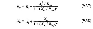
It can be justifiably assumed that (Xm/Riwf)2 = 0, so we get from the above equations
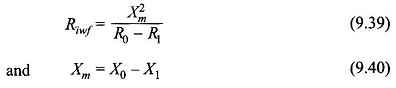
From the NL test data (V0, I0, P0) we can find from the circuit of Fig. 9.18(c).
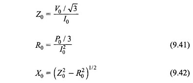
By substituting the values of R0 and X0 in Eqs. (9.37) and (9.38) respectively, we obtain Xm and Riwf.
Ri, the stator core loss resistance can be found out if the additional test of separating core loss from the windage and friction loss can be carried out.