Field Oriented Control of Induction Motor:
In the slip controlled drives using VSI or CSI discussed in the foregoing sections, the stator voltage or stator current is controlled using slip frequency. They are controlled in magnitude only. The stator current control does not take care of its phase position with respect to flux. The control does not provide satisfactory dynamic behaviour. There exists an oscillatory response to changes in the rotor frequency. The dynamic response may be improved using the principle of Field Oriented Control of Induction Motor where the stator current is controlled both in magnitude and phase position with respect to flux.
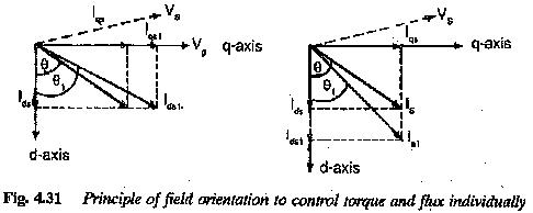
In Field Oriented Control of Induction Motor drives the stator current has the function of providing flux as well as torque. The induction motor will have an operation similar to that of a de motor if the stator current components, namely flux producing and torque producing are separately controlled (Fig. 4.31). This is actually the case in a dc motor where the torque depends on armature current and the flux on field current. There is an inherent decoupling between them but for the effects of armature reaction. These effects can be eliminated by means of compensating windings and there is perfect decoupling in a separately excited dc motor. This kind of decoupling is being attempted in the control of induction motors. The principle is called field orientation or vector control. This control improves the dynamic performance of the drive at all speeds. The stator current is decomposed into two components one along the d-axis and the other along the q-axis. The reference axes have been chosen such that the rotor flux is available completely along the direct axis. Its quadrature component is zero. Thus the component of current along the d-axis is the flux producing component and that along the q-axis is the torque producing component. By varying these components independently we can have independent flux control and torque control. These are depicted in Fig. 4.31(a) and (b). In the former the variation of flux is shown by varying direct axis component of current whereas in the latter the variation of q-axis component of stator current is depicted. Therefore the control of stator current amounts not only the variation of its magnitude but also its phase angle. The method is therefore called vector control.
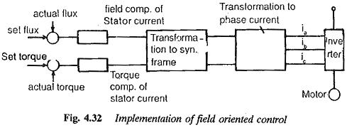
Vector control techniques employed to keep the air gap flux constant impart poor dynamic characteristics to the drive, as the torque follows the slip frequency with a delay. Techniques have been developed to keep the rotor flux constant. In these methods the torque follows without any delay, thereby improving the dynamic behaviour. Such a high quality dynamic behaviour is required for Field Oriented Control of Induction Motor used as actuators. Figure 4.32 depicts the implementation of the principle of field orientation. The actual value of rotor flux is compared with the reference value and the error so obtained is used to control the direct axis component of current. Normally this component is Maintained constant so that the rotor flux is constant. The quadrature axis component is controlled using the error signal obtained from the comparison of actual torque and reference torque. The components are in the synchronously rotating frame. Therefore the decoupling between flux producing and torque producing components of the armature current necessitates a reference coordinate system, and transformation of the quantities to this reference frame and finally to the stator frame,
In this control, which provides a very good dynamic behaviour without a torque transient, secondary flux is required, which can be made available in two ways:
1.direct measurement using flux sensing coils.
2.indirect estimation of the flux using a machine model, using easily measurable terminal quantities, such as voltages and currents.
The first method using direct measurement gives good results and is probably the most accurate control method available. The measurement is done by means of search coils, Hall probes or any other flux measuring techniques. The measured flux is used to effect the required decoupling between the torque producing and flux producing components of the stator current. The method is essentially insensitive to parameter variations. However, the cage motor loses its robustness and simplicity of construction.
If one tries to retain the robustness and simplicity of the motor, the flux is obtained using the second method. The rotor flux is estimated from the stator voltage vector, current vector and rotor speed. This estimated flux is fed to the torque controller. This approach is sensitive to errors in parameters. The rotor resistance, leakage reactance and other parameters must be accurately determined to achieve a performance equivalent to direct measurement. Unfortunately, the parameters of the motor used in the calculation are determined from no-load tests and do not represent the values of the parameters actually present at the operating point. Further, these parameters vary widely with saturation, temperature, frequency and current amplitude. The secondary flux level may be changed by the parameter variation. These variations in parameters result in erroneous flux control, which deteriorates the dynamic performance.
To avoid the errors due to variation of values of parameters (mainly rotor resistance), either due to incorrect estimation or due to operating conditions of the motor, automatic parameter identification or adaptation has been employed. The methods identify the changes in the performance due to the variation of parameters and correct the parameters accordingly. The error between the estimated value of flux and desired flux in the motor is made use of to correct the most influential parameter, which is the rotor resistance or rotor time constant, so that the machine model gives the required value of flux without any error.
Another method discussed recently is an on-line technique for establishing the exact value of rotor resistance of the induction motor. Identification is achieved by injecting a negative sequence current and detecting the negative sequence voltage. The value of the rotor resistance is calculated using the information. The Field Oriented Control of Induction Motor corrects the value of rotor resistance without the need for a thermal sensor..
The methods of state observer feed back are also employed for parameter identification.
With the advent of microprocessors (μps) and microcomputers it is nowadays possible to solve the problems connected with drives effectively with drive system are possible. The flux vector can be very easily determined. To achieve the matching of the model of the motor and the identification of rotor parameters by a correlation procedure, μps can be very effectively implemented without any additional measurements. The μps also facilitate the implementation of sophisticated algorithms for generating firing sequences of the inverter. Also, the elaborate process of field oriented control of the overall drive system has become economically feasible, as the expensive hardware used so far can now be substituted by software.
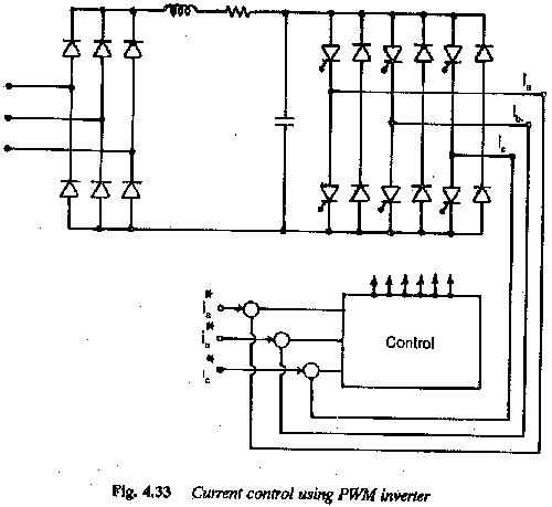
The field orientation can be very easily implemented with CSI feeding an Field Oriented Control of Induction Motor. As the PWM inverter has good dynamic behaviour, these are used with a current control on the output side. Figure 4.33 depicts the principle of current control using PWM inverter. This has the advantages of both VSI and CSI.
Induction motors in the flux weakening mode:
In the case of dc motors speeds above base speed are obtained by decreasing the field current at constant rated armature voltage. The torque developed decreases. A constant power mode can be realised in this speed range and is called flux weakening mode.
A similar behaviour can be observed in the case of induction motors. The voltage reaches its rated value for rated frequency. For frequencies above this value the inverter voltage is kept constant. The speed of the motor increases in proportion to the frequency. Due to the increase in the frequency, the air gap flux decreases. The torque at a given rotor frequency is inversely proportional to the square of the stator frequency and the power developed is not constant. The dynamic behaviour under weakened flux conditions is very poor. This can be improved by varying slip frequency for maximum torque in proportion to frequency.
A motor having current feeding has a good dynamic behaviour when there is reserve voltage at the inverter terminals. When once a certain value of upper frequency is reached, the back emf of the motor is equal to.the applied voltage and there is no reserve voltage for current control. The actual value of stator current and rotor flux deviate from the desired values and the drive has a poor dynamic behaviour. Improvement of dynamic performance of the motor in the field weakening mode is a problem of interest.
This can be done by controlling the amplitude of rotor flux and hence the back emf, so that sufficient voltage reserve is available in the speed range above base speed. Here also the direct and indirect methods of flux control can be used.