Field Energy and Mechanical Force:
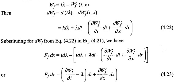
Field Energy and Mechanical Force – Consider once again the attracted armature relay excited by an electric source as in Fig. 4.4. The field produces a mechanical force Ff in the direction indicated which drives the mechanical system (which may be composed of passive and active mechanical elements). The mechanical work done by the field when the armature moves a distance dx in positive direction is
This energy is drawn from the field by virtue of change dx in field configuration. As per the principle of energy conservation
It may be seen that Ff dx is the gross mechanical output, a part of which will be lost in mechanical friction.
From Eq. (4.10)
Because the incremental changes di and dx are independent and di is not present in the left-hand side of Eq. (4.23), its co-efficient on the right-hand side must be zero i.e.
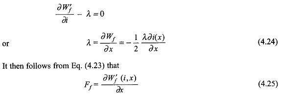
This expression for mechanical force developed applies when i is an independent variable, i.e. it is a current excited system
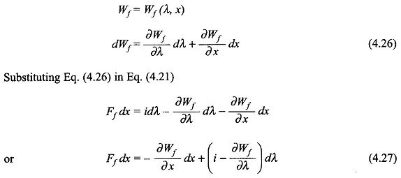
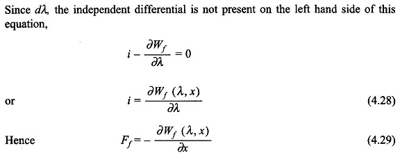
In this form of expression for the mechanical force of field origin, λ is the independent variable, i.e. it is a voltage-controlled system as voltage is the derivative of λ.
In linear systems where inductances are specified it is more convenient to use coenergy for finding the force developed (Eq. (4.25)). If the system is voltage-controlled, the current can be determined by writing the necessary circuit equations.
It is needless to say that the expressions of Eqs (4.25) and (4.29) for force in a translatory system will apply for torque in a rotational system with x replaced by angular rotation θ.
Direction of Mechanical Force Developed:
With reference to Eq.(4.29) it immediately follows that Ff is positive (i.e. it acts in the positive reference direction of x) if ∂Wf(λ, x)/∂x is negative which means that stored energy of the field is reduced with increase of x while flux linkages λ, are held fixed. In the particular case of Fig. 4.4 as x increases (i.e., the armature moves towards left), the field energy for fixed λ is reduced because the air-gap is reduced. It means that Ff in this case acts in the positive direction. It is therefore, concluded that the mechanical force produced by the field acts in a direction to reduce field energy or in other words the system seeks a position of minimum field energy. Similarly, it can be concluded from Eq. (4.26) that the system seeks a position of maximum coenergy.
Also in Fig. 4.4, the force acts in a direction to increase x thereby reducing the magnetic circuit reluctance and increasing the coil inductance.
Determination of Mechanical Force:
Nonlinear case: It was seen above that the mechanical force is given by the partial derivatives of coenergy or energy as per Eqs (4.26) and (4.29). In the general nonlinear case, the derivative must be determined numerically or graphically by assuming a small increment Δx. Thus
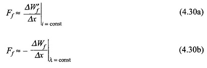
These two expressions will give slightly different numerical values of Ff because of finite Δx. Obviously Ff is the same in each case as Δx —> 0. Calculation of Ff by Eq. (4.30a) is illustrated in Ex. 4.2.
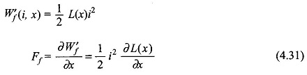
Linear case: From Eq. (4.17)
 .
.
From Eq. (4.31), it is obvious that the force acts in a direction to increase the inductance of the exciting coil, a statement already made.
Alternatively from Eq. (4.14)
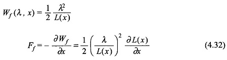
It may be seen that Eqs (4.31) and (4.32) are equivalent as i = λ/L.
Also from Eq. (4.12)
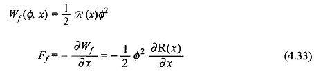
It must be remembered here that there is no difference between λ as independent variable or Φ as independent variable as these are related by a constant (λ = NΦ). It follows from Eq. (4.33) that the force acts in a direction to reduce reluctance of the magnetic system, a statement that has been made already.
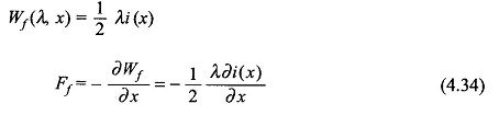
Another expression for Ff can be derived as below:
From Eq. (4.12)
Mechanical Energy:
When the armature in Fig. 4.4 is allowed to move from position xa to xb with the coil current remaining constant at i0, the mechanical energy output is
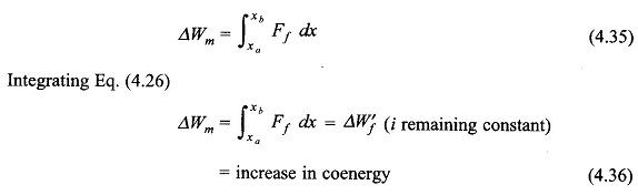
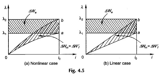
The graphical representation of Eq. (4.36) is given in Fig. 4.5(a) for the general nonlinear case while Fig. 4.5(b) gives the linear case. In each case the electrical energy input is
![]()
For the linear case, it follows from the geometry of Fig. 4.5(b) that
![]()
which means that half the electrical energy input gets stored in the field and the other half is output as mechanical energy. In this kind of operation the armature must move from position xa to xb infinitely slowly for the excitation coil current to remain constant.
Let now the armature in Fig. 4.4 be allowed to move from xa and xb with coil flux linkage λ remaining constant. Integrating Eq. (4.29),
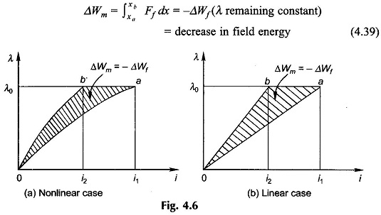
This is illustrated in Fig. 4.6(a) for the general nonlinear case and in Fig. 4.6(b) for the linear case. In each case
For λ to remain constant, the armature must move from xa to xb in zero time. Since there is no electrical input, the mechanical energy output is drawn from the field energy which reduces by an equal amount.
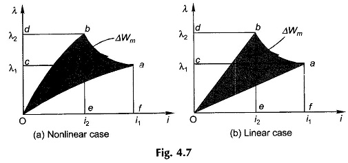
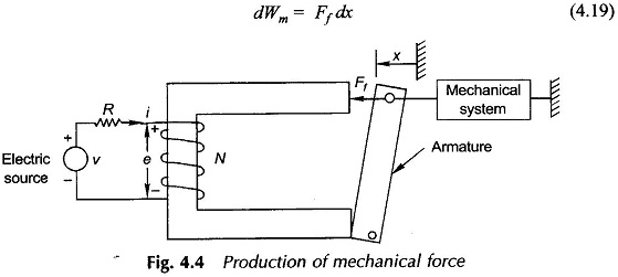
The actual armature movement lies between the two ideal cases illustrated above. The corresponding i-λ relationship is a general path from a to b as shown in Figs 4.7(a) and (b). In this general case
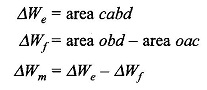
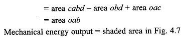
Since ab is a general movement, this area which represents the mechanical energy output has to be computed graphically or numerically.