Subsystems of Thermal Power Plant:
The Subsystems of Thermal Power Plant are the auxiliary plants required for the plant for its proper operation and for the increase of their efficiency.
Some of the sub systems are as follows:
Boiler Accessories:
The appliances used to increase the efficiency of the boiler are known as boiler accessories.
The important boiler accessories are:
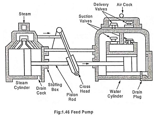
1. Feed pumps
Feed pumps are used to deliver water to the boiler. It is essential to use a feed pump because the quantity of water supplied should meet amount of water evaporated and supplied to the engine.
Basically two types of pump are in use
- Reciprocating feed pump
- Rotary feed pump
Reciprocating feed pump consists of a cylinder and a piston. The piston displaces water as it reciprocates inside the cylinder. The reciprocating pump may be of two types.
- Single acting pump and
- Double acting pump
They are continuously run by steam from the same boiler to which water is to be fed.
Rotary feed pumps are of centrifugal types and are commonly run either by a small steam turbine or by electric motor.
The duplex feed pump is a double acting reciprocating feed pump. In this pump, there are two simple engine cylinders placed side by side. The pressure of steam acts directly on the piston to pump the water. Each pump has one steam cylinder and water cylinder.
2. Economiser
It is a device in which the waste heat of the flue gases is utilized for heating feed water.
The uses of a economiser has many advantages
- The temperature range between various parts of the boiler is reduced which results in reduction of stress on the inner wall of boiler drum due to uneven thermal expansion.
- Evaporate capacity of the boiler is increased.
- Less fuel is required to turn the feed water into steam.
- Overall efficiency of the plant is increased.
Greens’ vertical tube economiser is shown in Fig.1.47.
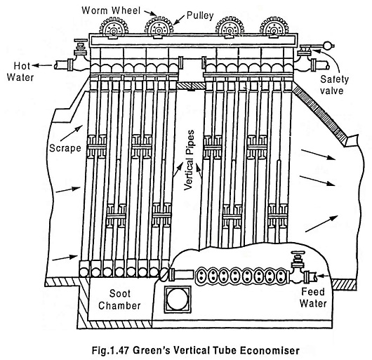
Economiser is used to preheat the feed water using furnace flue gases.
It consists of a large number of cast iron vertical tubes. These tubes are connected at the top and bottom by two horizontal pipes and are placed in the main flue between the boiler and the chimney. The water is pumped to the lower horizontal pipe and then flows through the vertical tubes. The water becomes heated by absorbing heat from the flue gas which passes over the tubes. The hot water enters the upper horizontal pipe and is fed to the boiler. To remove the deposits of soot from the surface of the tubes, scrapers are provided. These scrapers move up and down slowly by means of a chain passing over the pulleys to remove the soots.
3. Air preheater
In this subsystems of thermal power plant, air preheater is an auxiliary system that increase the temperature of air before it enters the furnance. It is generally placed after the economiser – i.e. in between economiser and chimney.
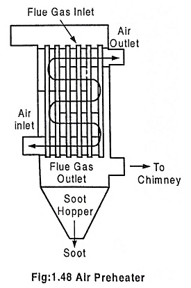
Preheated air accelerates the combustion and facilitates the burning of coal.
There are two types of air preheaters (a) recuperative and (b) regenerative.
In a recuperative air preheater, the heat from the flue gases is transferred to air through a metallic medium. In a regenerative air preheater, air and flue gases are made to pass alternatively through the matrix. When the hot gases pass through the matrix it transfers heat to the cold air. The preheating of air helps the burning of low grade fuel, thus permitting a reduction in excess air and thereby increasing the efficiency. The overall efficiency of the plant may be increased by 10% by its one.
4. Super heater
In this subsystems of thermal power plant, the function of the super heater is to increase the temperature of the steam above its saturation point.
Super heater steam has the following advantages.
- Steam consumption by the turbine is reduced.
- Loss due to condensation is reduced.
- Erosion of turbine blade is eliminated.
- Efficiency of the plant is increased.
A superheater is located in the path of the hot furnace gases. Fig.1.49. shows a Sudgen’s superheater.
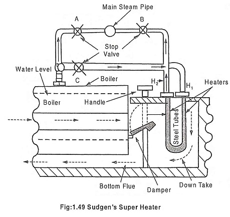
When the superheater is in operation, the valve A is closed. The wet steam from the boiler enters the right heater through the valve C. The steam flows through the number of U – tubes where it receives heat from the hot flue gases and becomes superheated. The superheated steam then passes to the discharge header and then to the main steam pipe connected to one end of the discharge header through the valve B.
The overheating of the superheater tubes is prevented by using a damper which is controlled by the Handle. It controls the flow of flue gases to the superheater chamber. When the damper is horizontal, the hot flue gases pass over the U tubes (superheated tubes). But when the damper is vertical, the hot flue gases directly pass to the bottom flue without superheating. Thus degree of superheating is controlled by changing the position of damper.
5. Steam separator
The steam generated may be either wet steam (or) dry steam (or) superheated steam. The wet steam must be separated from the dry steam before letting it enter the main steam line. This separation is done by steam separator. It prevents the wet steam from entering the main steam line, thus prevents the turbine blades from corrosion.
6. Injector
An injector is used to feed water into vertical and locomotive boilers using steam from the same boiler. It consists of three jets – steam jet, suction jet, combining and delivery jet.
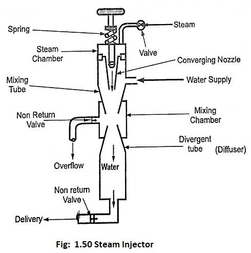
The steam expands in the steam nozzle where its pressure drops but its velocity increases. As the steam passes across space between steam and suction nozzles a vacuum is developed in the suction chamber. The water is drawn into the suction chamber from the feed tank. The high speed steam jet takes the water along with the steam into the combining and delivery jet.
Here the steam is condensed and mixed with the water. The delivery jet is so designed that a considerable amount of kinetic energy of the jet changes into pressure energy which is sufficient to force the water in the boiler. There will be no overflow when the steam and water are in proper ratio. For the injector to act properly there is a definite relation between the quantity of steam and water entering the injector.
7. Wagon tippler
It is the machine used to tip the coal from the wagon. The coal tipped is directly fed to conveyor belt which takes the coal to the coal mills.
8. Coal mills
Coal feeds in the coal mill are converted into pulverised form and they are fed to the boiler furnance.
9. Boiler furnance
It is the chamber in which fuel burns and fire blows.
10. Boiler Drum
It contains feed water for boiling.
11. Electro Static Precipitator (ESP)
ESP is located between the boiler and the chimney, it extracts the fly ash from flue gases and thus prevents the fly ash from entering the atmosphere.
12. Chimney
It is used to release flue gas into the atmosphere.
Different types of Chimney are
- Steel Chimney
- Site constructed chimneys
- Plastic chimneys
13. Cooling Tower
It is used to cool the water and its height is about 140 meters.
14. Low pressure heater
It is used to increase the temperature of water at low pressure, in this way efficiency of system increases.
15. High pressure heater
In HP heater, the temperature of water increases at high pressure. Thus efficiency further increases.
16. Deaerator
It is used to remove air from water which is entrapped in the water molecules. It is very important part because the entrapped air affects air drum badly.