LCR Bridge:
Basic LCR Bridge (Skeleton Type) : A simple bridge for the measurement of resistance, capacitance and inductance may be constructed with four resistance decades in one arm, and binding post terminals to which external resistors or capacitors may be connected, to complete the other arms. Such a skeleton arrangement is useful in the laboratory, since it permits the operator to set up a number of different bridge circuits simply by plugging standards and unknown units into the proper terminals.
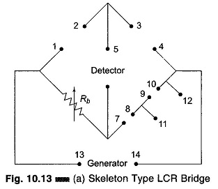
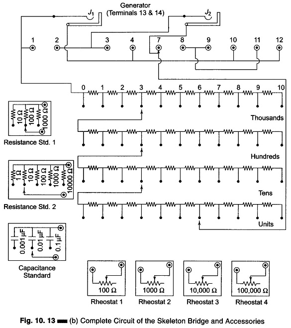
The schematic circuit diagram of a skeleton type bridge and its accessories for the measurement of R, L and C is shown in Figs 10.13(a) and 10.13(b).
In Fig. 10.13(a), Rb is self contained. The other arms are completed by connecting the unknown and standard component to terminals 1-2, 3-4, 7-8, 9-10, and 11-12, a null detector to 5-6, and a generator to 13-14. This bridge can be used for both ac and dc measurements.
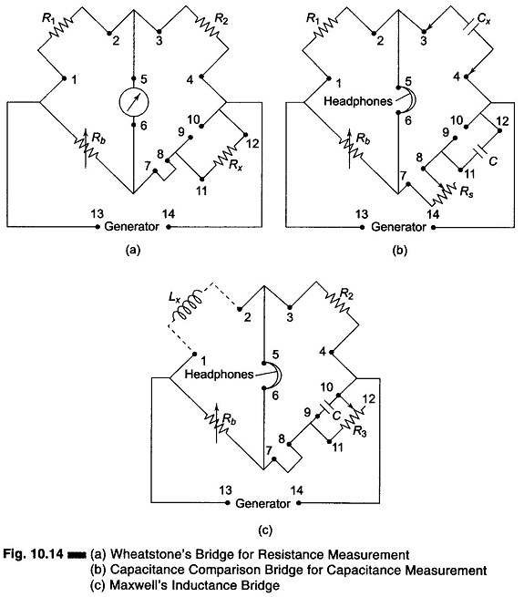
By proper arrangement of the bridge arms, the Wheatstone’s bridge shown in Fig. 10.14(a) may be set up for resistance measurement (ac and dc), a comparison circuit shown in Fig. 10.14(b) for measurement of C, and a Maxwell’s circuit shown in Fig. 10.14(c) for the measurement of inductance L.
The skeleton bridge permits resistance measurements from 0.001 Ω to 11.11 MΩ, capacitance measurements from 1 pf (if stray capacitance permits) to 1111 μF and inductance measurements from 1 μH (if stray inductance and capacitance permit) to 111.1 H.
The bridge accessories are shown in Fig. 10.13(b). There are two switched resistance standard boxes (one 10 – 100 – 1000 Ω precision resistance and another 1 – 10 – 100 – 1000 – 10000 Ω precision resistance), one switched capacitor standard box containing 0.001 – 0.01 – 0.1 μF, a close tolerance capacitor, and four mounted dial calibrated rheostats having values of 100 – 1 k – 10 k – 100 kΩ.
For dc measurements 1.5 – 7.5 V batteries are used and connected to terminals 13 – 14. A centre zero 50 – 0 – 50 or 100 – 0 – 100 dc microammeter is connected to terminals 5 – 6.
For ac measurements of R, L and C connect a signal source or AF oscillator tuned to a frequency of 1 kHz to terminals 13 – 14 and a null detector (head-phone, AC VTVM, CRO, etc) to terminal 5 – 6.