Bridge Controlled Error Detection:
Bridge Controlled Error Detection – Whenever a bridge is unbalanced, a potential difference exists at its output terminal. The potential difference causes current to flow through the detector (say, a galvanometer) when the bridge is used as part of a measuring instrument. When the bridge is used as an error detector in a control circuit, the potential difference at the output of the bridge is called an error signal, as in Fig. 11.14.
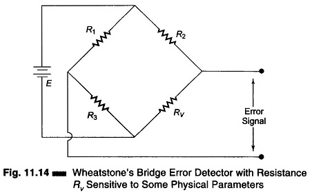
Passive circuit elements such as strain gauges, temperature sensitive resistors (thermistors) and photo resistors, produce no output voltage. However, when used as one arm of Wheatstone’s bridge, a change in their sensitive parameter (heat, light, pressure) produces a change in their resistances. This causes the bridge to be unbalanced, thereby producing an output voltage or an error signal.
Resistor Rν in Fig. 11.14 may be sensitive to one of many different physical parameters, such as heat or light. If the particular parameter to which the resistor is sensitive, is of a magnitude such that the ratio R2/Rν equals R1/R3, then the error signal is zero. If the physical parameters changes, Rν also changes. The bridge then becomes unbalanced and an error signal occurs. In most control applications the measured and controlled parameter is corrected, restoring Rν to the value that creates a null condition at the output of the bridge.
Since Rν varies by only a small amount, the amplitude of the error signal is normally quite low. It is therefore amplified before being used for control purposes.