Automatic Bridge Circuit:
The bridges discussed so far require that the controls be adjusted for balance after each capacitor (or other devices being tested) is connected to the bridge. In effect, they are manual. In recent years a number of automatic bridges have been developed. These Automatic Bridge Circuit provide an automatic readout without adjustment of balance controls.
In some cases, the automatic bridges also provide a Binary Coded Digital (BCD) readout to external equipment. Automatic Bridges are similar in operation to digital meters. To understand their operation, it is necessary to understand logic and digital circuit methods.
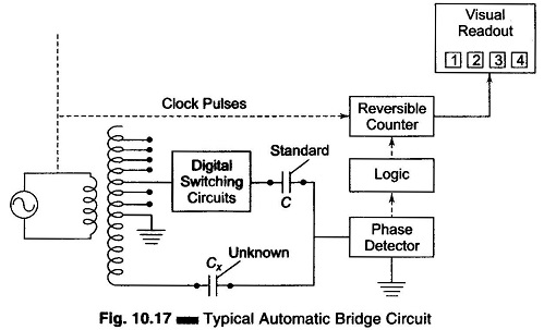
A typical automatic bridge circuit is shown in Fig. 10.17. The circuit is transformer-ratio-arm bridge for the automatic measurement of capacity. The circuit is in balance when the currents through the standard capacitor and the unknown capacitor are equal, so that the current in the phase detector is zero. The range is chosen automatically by relays that select decade taps on the ratio transformer. The phase detector determines whether the current passing through the unknown arm, of the bridge is higher or lower than that through the standard arm and produces an error signal that indicates whether more or less voltage is required on the standard capacitor to reach a balance.
This information is used by a decade counter that controls the voltage on the standard capacitor through electronic switching circuits. The counter then counts in the direction which minimises the error signal, until a balance is reached. At balance, the value of the unknown is displayed on an in-line digital readout that indicates capacitance. This information is also presented in BCD form for use with printers and other data handling equipment’s.