Different Modes of Operation of Electronic Counter:
The decade counter can be easily incorporated in a commercial test instrument called an electronic counter. A decade counter, by itself, behaves as a totaliser by totalling the pulses applied to it during the time interval that a gate pulse is present. Typical Different Modes of Operation of Electronic Counter are totalising, frequency, period, ratio, time interval and averaging.
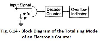
Totalising:
In the totalising modes of operation of electronic counter, as shown in Fig. 6.14, the input pulses are counted (totalised) by the decade counter as long as the switch is closed. If the count pulse exceeds the capacity of the decade counter, the overflow indicator is activated and the counter starts continue again.
Frequency Mode:
If the time interval in which the pulses are being totalised is accurately controlled, the counter operates in the frequency mode. Accurate control of the time interval is achieved by applying a rectangular pulse of known duration to the AND gate, as shown in Fig. 6.15, in place of the dc voltage source.
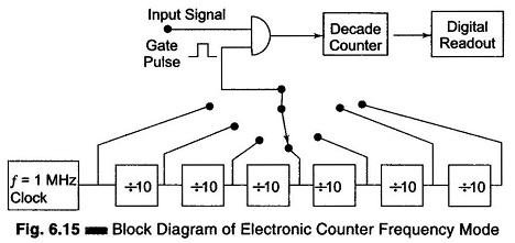
This technique is referred to as gating the counter. A block diagram of an electronic counter operating in the frequency mode is shown in Fig. 6.15. The frequency of the input signal is computed as

Where
- f = frequency of the input signal
- N = pulse counted
- t = duration of the gate plate
Ratio Mode:
The ratio modes of operation of electronic counter simply displays the numerical value of the ratio of the frequencies of the two signals.
The low frequency signal is used in place of the clock to provide a gate pulse. The number of cycles of the high frequency signal, which are stored in the decade counter during the presence of an externally generated gate pulse, is read directly as a ratio of the frequency. A basic circuit for the modes of operation of electronic counter is shown in Fig. 6.16.
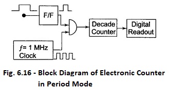
Period Mode:
In some applications, it is desirable to measure the period of the signal rather than its frequency. Since the period is the reciprocal of the frequency, it can easily be measured by using the input signal as a gating pulse and counting the clock pulses, as shown in Fig. 6.16.
The period of the input signal is determined from the number of pulses of known frequency or known time duration which are counted by the counter during one cycle of the input signal. The period is computed as

Where
- N = pulse counted
- f = frequency of the clock
Time Interval Mode:
The time interval mode of operation measures the time elapsed between two events. The measurement can be done using the circuit of Fig. 6.17.
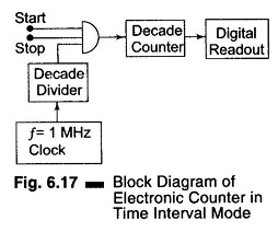
The gate is controlled by two independent inputs, the start input, which enables the gate, and the stop input which disables it. During the time interval between the start and stop signal, clock pulses accumulate in the register, thus providing an indication of the time interval between the start and stop of the event.
Electronic counters find many applications in research and development laboratories, in standard laboratories, on service benches and in everyday operations of many electronics installations.
Counters are used in communication to measure the carrier frequency, in a digital system to measure the clock frequency, and so on.