Self Controlled Synchronous Motor Drive:
A Self Controlled Synchronous Motor Drive employing a load commutated thyristor inverter is shown in Fig. 7.10. In large power drives wound field synchronous motor is used. Medium power drives also employ permanent magnet synchronous motor. The drive employs two converters, which are termed here as source side converter and load side converter. The source side converter-is a 6-pulse line-commutated thyristor converter. For a firing angle range 0 ≤ αs ≤ 90∘, it works as a line-commutated fully controlled rectifier delivering positive Vds and positive Id, and for the range of firing angle 90∘ ≤ αs ≤180∘ it works as a line-commutated inverter delivering negative Vds and positive Id.
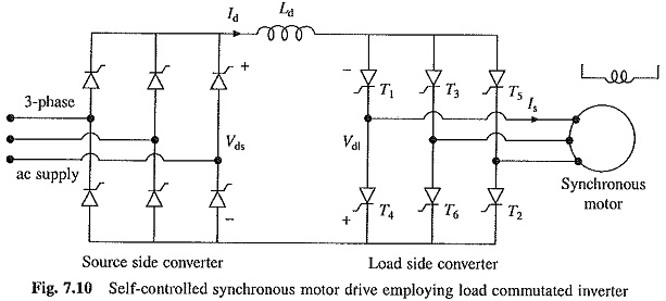
When Self Controlled Synchronous Motor Drive operates at a leading power factor, thyristors of the load side converter can be commutated by the motor induced voltages in the same way, as thyristors of a line-commutated converter are commutated by line voltages. Commutation of thyristors by induced voltages of load (here load is a motor) is known as load commutation. Firing angle is measured by comparison of induced voltages in the same way as by the comparison of line voltages in a line commutated converter. Converter operates as an inverter producing negative Vdl and carrying positive Id for 90∘ ≤ αl ≤ 180∘. For 0 ≤ αl ≤ 90∘ it works as a rectifier giving positive Vdl. For 0 ≤ αs ≤ 90∘, 90∘ ≤ αl ≤ 180∘ and with Vds > Vdl, the source side converter works as a rectifier and load side converter as an inverter, causing power to flow from ac source to the motor, thus giving motoring operation. When firing angles are changed such that 90∘ ≤ αs ≤ 180∘ and 0∘ ≤ αl ≤ 90∘, the load side converter operates as a rectifier and the source side as an inverter. Consequently, the power flow reverses and machine operates in regenerative braking. The magnitude of torque depends on (Vds — Vdl). Speed can be changed by control of line side converter firing angles.
When working as an inverter, the firing angle has to be less than 180° to take care of commutation overlap and turn-off of thyristors. It is common to define a commutation lead angle for load side converter as
![]()
If commutation overlap is ignored, the input ac current of the converter will lag behind input ac voltage by angle αl. Since motor input current has an opposite phase to converter input current, the motor current will lead its terminal voltage by an angle βl. Therefore, the motor operates at a leading power factor.
Lower the value of βl. higher the motor power factor and lower the inverter rating. The commutation overlap for the load side converter depends on the subtransient inductance of the motor. The motor is provided with a damper winding in order to reduce subtransient inductance. This allows operation with a substantially lower value of βl. The damper winding does not play its conventional roles of starting the machine as an induction motor and to damp oscillations, because rotor and rotating field speeds are always the same as explained later. In a simple control scheme, the drive is operated at a fixed value of commutation lead angle βlc for the load side converter working as an inverter and at βl = 180° (or αl = 0°) when working as a rectifier. When good power factor is required to minimize converter rating, the load side converter when working as an inverter is operated with Constant Margin Angle Control. If commutation overlap of the thyristor under commutation is denoted by u, then the duration for which the thyristor under commutation is subjected to reverse bias after current through it has fallen to zero is given by
![]()
For successful commutation of thyristor
![]()
where tq is the turn-off time of thytistors and ω the frequency of motor voltage in radians/sec. Since u is proportional to Id, for a given Id, βl can be calculated such that the thyristor under commutation is reverse biased for a duration γmin which is just enough for its commutation. This in turn minimizes βl and maximizes motor power factor. Since γ is kept constant at its minimum value γmin, the control scheme is called constant margin angle control.
The dc link inductor Ld reduces the ripple in the dc link current Id and prevents the two converters from interfering with each other’s operation. Because of the presence of inductor in the dc link, the load side converter when working as an inverter, behaves essentially as a current source inverter of Fig. 6.45, except that thyristor commutation is now performed by motor induced voltages. Consequently, the motor phase current has six step waveform of Fig. 6.45(b). Because of the dc current through Ld, the ac input current of source side converter also has a six step current waveform.
The dc line current Id flows through the machine phase for 120° in each half cycle. Fundamental component of motor phase current Is has following relationship with Id
For machine operation in the self-controlled mode, rotating field speed should be the same as rotor speed. This condition is realized by making frequency of the load side converter output voltage equal to the frequency of voltage induced in the armature. Firing pulses are therefore generated either by comparison of motor terminal voltages (as induced voltages are not directly accessible) or by the rotor position sensors. Self control is ensured when firing pulses are generated by the comparison of motor terminal voltages (as induced voltages are not directly accessible). Alternatively firing pulses are generated by rotor position sensors, which are stationary and suitably aligned with the armature winding. The frequency of induced voltages depends on the speed of rotor (or rotor field) and their phase depends on the location of rotor poles with respect to the armature winding. Hence, signals generated by rotor position sensors have the same frequency as that of the induced voltages and they have a definite phase with respect to induced voltages. Load side converter thyristors are fired in the sequence of their numbers with 60° interval. Therefore, for the control of load side converter thyristors, in all six rotor angular positions are required to be detected per cycle of the induced voltage. The Hall-effect sensors can detect the magnitude and direction of a magnetic field. Hence, three Hall-effect sensors can detect the six rotor positions. The sensors are mounted at 60° electrical intervals and aligned suitably with armature winding.
As stated earlier the load side converter and the current source inverter of Fig. 6.45 perform essentially the same function.. The only difference between the two is that while the former uses the load commutation, the later uses forced commutation.
Load commutation has a number of advantages over forced commutation:
-
it does not require commutation circuits,
-
frequency of operation can be higher, and
-
it can operate at power levels beyond the capability of forced commutation.
Load side converter performs somewhat similar function as commutator in a dc machine. The load side converter and Self Controlled Synchronous Motor Drive combination functions similar to a dc machine. First, it is fed from a dc supply and secondly like a dc machine the stator and rotor fields remain stationary with respect to each other at all speeds. Consequently, the drive consisting of load side converter and synchronous motor is known as Commutator Less DC Motor.
At low speeds, motor induced emf will be insufficient to commutate the thyristors of load side converter, therefore, at start and for speeds below 10% of base speed, the commutation of load side converter thyristors is done by forcing the current through conducting thyristors to zero. This is realised by making source side converter to work as inverter each time load side converter thyristors are to be turned off.
For example thyristors T1 and T2 are to conduct together for 60° electrical. After 60°, source side converter will be made to work as an inverter, which will reverse Vds and turn-off thyristors T1 and T2. Now the source side converter operation is brought back to rectification and gate pulses are released to T2 and T3 to turn them on and make them conduct together for next 60° electrical. Since frequency of operation of load side converter at low motor speeds is very low compared to source frequency, such an operation can be realized. This operation of the inverter can be termed as Pulsed Mode. This mode of operation requires rotor position sensors. Therefore, even when the normal operation above 10% of base speed is implemented by sensing motor terminal voltages, rotor position sensors will be needed to realize pulsed mode.
The dc supply to the field can be provided from a controlled rectifier through slip-rings and brushes. Alternatively, brushless excitation system consisting of diode bridge mounted on the rotor and therefore rotating with the rotor and supplied by a rotating transformer can be used. The field current is controlled by controlling the input voltage of the transformer by feeding it from an ac voltage regulator. The brushless excitation eliminates slip-rings and brushes and associated maintenance.
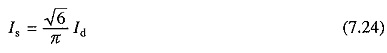
A closed-loop speed control scheme is shown in Fig. 7.11. It employs outer speed control loop and inner current control loop with a limiter, like a dc motor (Fig. 5.47). The terminal voltage sensor generates reference pulses of the same frequency as the machine-induced voltages. The phase delay circuit shifts the reference pulses suitably to obtain control at a constant commutation lead angle βlc. Depending on the sine of speed error, βlc is set to provide motoring or braking operation. Speed ωm can be sensed either from the terminal voltage sensor or from a separate tachometer. An increase in reference speed ωm produces a positive speed error.
βlc value is set for motoring operation. The speed controller and current limiter set the dc link current reference at the maximum permissible value. The machine accelerates fast. When close to the desired speed, the current limiter desaturates and the drive settles at the desired speed and at the dc link current which balances motor and load torques. Similarly a reduction in reference speed produces a negative speed error. This sets βlc for regenerative braking operation (i.e. 180°) and the motor decelerates. When speed error changes sign βlc value is set for motoring operation and the drive settles at the desired speed.
High efficiency, four-quadrant operation with regenerative braking, high power ratings (up to 100 MW) and ability to run at high speeds (6000 rpm) are some important advantages of this drive. Some prominent applications are high speed and high power drives for compressors, blowers, fans, pumps, conveyers, steel rolling mills, main line traction, ship propulsion and aircraft test facilities.
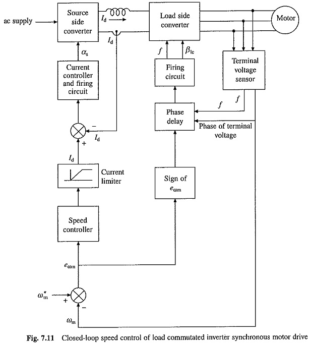
At very high power levels, harmonics generated at the source and motor terminals require special attention. Single line diagram of a high power drive is shown in Fig. 7.12. The source side harmonics are reduced by using a 12-pulse converter. For this two six-pulse converters are connected in series. The’supply for the converters is obtained through a transformer with primary connected in star and having two secondary windings, one connected in star feeds one six pulse converter and another connected in delta feeds another six pulse converter. This way 30° phase shift is provided between the input voltages of two six-pulse converters. The input current waveforms of two converters and source current are shown in Fig. 7.12. The source current is more close to sinusoidal compared to six-pulse converter.
The harmonics in motor current produce torque pulsations and losses in rotor and damper windings due to induced harmonic currents. These effects are minimized by using a Self Controlled Synchronous Motor Drive equipped with two three phase windings on stator with a phase shift of 30° between their axes and feeding them from two series connected six-pulse load commutated converters with their output current phase shifted by 30° (Fig. 7.12). The resultant stator mmf has twelve pulse waveform. Therefore, torque pulsations and rotor and damper winding losses are reduced. When the motor has only single winding, it can be supplied with 12-pulse current by connecting the series connected six-pulse converters with the motor via transformers in the same way as mentioned above for source side converters.