Self Controlled Synchronous Motor Drive Employing a Cycloconverter:
Self Controlled Synchronous Motor Drive Employing a Cycloconverter as shown in Fig. 7.13. Firing pulses are generated either by comparison of the motor terminal voltages or by rotor position senors as in the case of drive.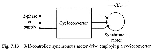
Cycloconverter control has the advantages of smooth low speed operation, four-quadrant operation with regenerative braking and good dynamic response. But it has low speed range and because it uses large number of thyristors it becomes economically acceptable only when the drive rating is high. A synchronous motor without the damper winding is used, because the damper winding reduces the inductance of the machine, and therefore, its ability to filter out harmonics in the output voltage of cycloconverter. Since the drive operates in self-controlled mode, the damper winding is not needed for its conventional roles.
The drive is employed in low speed gearless drives for ball mills in cement plants, mine hoists, reversing rolling mills requiring fast dynamic response and in ships equipped with diesel generator fed Self Controlled Synchronous Motor Drive Employing a Cycloconverter. These drives have power ratings in the megawatt range. At such high power levels, considerable saving in cycloconverter cost is obtained by operating the motor at unity power factor by adjusting the field current.
A typical rating of a synchronous motor for a ball mill in a cement plant is: 8750 hp, unity power factor, 14.5 rpm, 4.84 Hz, 1900 V and 40 poles. A cycloconverter is ideally suitable for such a low frequency supply. Earlier gears were employed to get low speed operation. Absence of gears in this drive reduces the cost and maintenance requirements. Because of similarity with an ac commutator motor, the drive is also known as ac commutatorless motor.
Permanent Magnet AC Motor Drives:
Permanent magnet synchronous motors are now commonly known as permanent magnet ac (PMAC) motors.
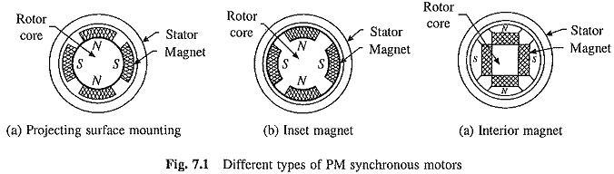
They are classified based on the nature of voltage induced in the stator as Sinusoidally Excited and Trapezoidally Excited; in the former induced voltage has a sinusoidal waveform and in the later induced voltage has trapezoidal waveform, These PMAC motors are commonly known as Sinusoidal PMAC and Trapezoidal PMAC motors. A sinusoidal PMAC motor has distributed winding (similar to wound field synchronous motor) in the stator. It employs rotor geometries such as inset or interior shown in Fig. 7.1. Rotor poles are so shaped that the voltage induced in a stator phase has a sinusoidal waveform. The stator of a trapezoidal PMAC motor has concentrated windings and a rotor with a wide pole arc. The voltage induced in the stator phase has a trapezoidal waveform. It employs rotor geometries such as surface magnets shown in Fig. 7.1.
The speed of PMAC motors is controlled by feeding them from variable frequency voltage/currents. They are operated in self-controlled mode. Rotor position sensors are employed for operation in self-control mode. Alternatively induced voltage can be used to achieve self-control.
Different inverter/converter circuits for PMAC motors are drawn using a power transistor. The current trend is to use MOSFET for low voltage and low power applications and IGBT for others.
In the past self-controlled variable frequency drives employing a sinusoidal PMAC motor were also called brushless dc motor drives. They are now simply called sinusoidal PMAC motor drives. The self-controlled variable frequency drives employing a trapezoidal PMAC motor are now called brushless dc motor drives or trapezoidal PMAC motor drives.