Application of LCR Circuit:
Here, we consider the Application of LCR Circuit containing a source, resistors, inductors and capacitors. Before discussing the formation of differential equation for the circuits, let us discuss the υ-i relationships for basic network elements.
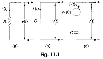
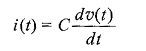
Resistor: The resistor shown in Fig. 11.1(a) has the following relation between voltage and current.
![]()
where R is given in ohms.
Capacitor: For the capacitor shown in Fig. 11.1(b), the υ-i relationships are
or
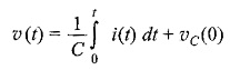
where υC(0) is the initial voltage across the capacitor. The capacitor can be represented as shown in Fig. 11.1(c).
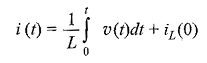
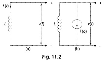
Inductor: For the inductor shown in Fig. 11.2(a), the υ-i relationships are
or
![]()
where iL(0) is the initial current passing through the Application of LCR Circuit. The inductor can be represented as shown in Fig. 11.2(b).
We now consider the circuit shown in Fig. 11.3
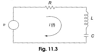
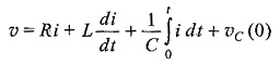
By applying Kirchhoff s law to the circuit in Fig. 11.3, we have
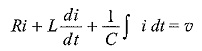
If the capacitor has no initial charge, the above equation becomes
Differentiating the above equation, we get
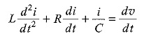
This is a second order linear differential equation in the single dependent variable, i.