High Voltage Schering Bridge:
In the power frequency range (25 to 100 Hz) High Voltage Schering Bridge is a very versatile and sensitive bridge and is readily suitable for high voltage measurements. The stress dependence of K′ or εr and tan δ can be readily obtained with this bridge.
The schematic diagram of the High Voltage Schering Bridge is shown in Fig. 9.11. The lossy capacitor or capacitor with the dielectric between electrodes is represented as an imperfect capacitor of capacitance Cx together with a resistance rx. The standard capacitor is shown as Cs which will usually have a capacitance of 50 to 500 pF.
The variable arms are R4 and C3 R3. Balance is obtained when
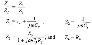
The balance equations are
The loss angle,
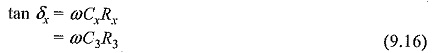
Usually δx will be small at power frequencies for the common dielectrics so that
![]()
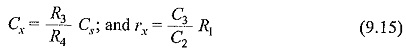
The lossy capacitor which is made as an equivalent Cx in series with rx can be represented as a parallel combination of Cx and Rx where the parallel combination Rx is found to be
![]()
with Cx having the same value.
The normal method of balancing is by fixing the value of R3 and adjusting C3 and R4, If R3 is chosen as (1000/π) ohms for ω = 100 π and if C3 is expressed in microfarads, then tan δ = 0.1 C3 giving a direct reading of tan δ. R4 will be a decade box with 5 to 6 decade dials. The maximum value of R4 is limited to 104 Ω and the lowest value will not be less than 0.01 Ω. This range adequately takes care of the errors due to contact resistances as well as the stray capacitance effects across R4 which are usually very small. It is important to see that the resistances are pure and not reactive and the standard capacitor has negligible tan δ (air or gas filled capacitor is used).
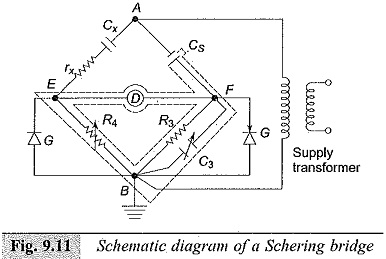
The arrangement shown in Fig. 9.11 is suitable when the test specimen is not grounded. The standard capacitor Cs is usually a three terminal capacitor. The low voltage arms of the bridge (R4 and R3 C3) and the detector are enclosed in grounded shielded boxes to avoid stray capacitances during the measurements. The detector is either a vibration galvanometer or in modern bridges a tuned electronic null detector of high sensitivity. The protective gaps G are so arranged that the low voltage arms are protected from high voltages in case the test objects fail. The values of the impedances of the low voltage arms are such that the voltage drop across EB or FB does not exceed 10 to 20 V. The arms will be usually rated for a maximum instantaneous voltage of 100 V.
For a very accurate measurement of the dissipation factor at power frequency, the stray and grounded capacitances should be eliminated and the indirect capacitive and inductive coupling of the arms are to be minimized to a level lower than the accuracy of the bridge arms. In this High Voltage Schering Bridge the main source of error is the around capacitance of the low voltage terminals of high voltage arms, i.e. the stray capacitances from E and F to ground. These are eliminated by shielding the low voltage arms using doubly shielded cables for connections and using the “Wagner earthing device“. Sometimes, compensation for the stray capacitances is given by providing a parallel R-L circuit across R4.
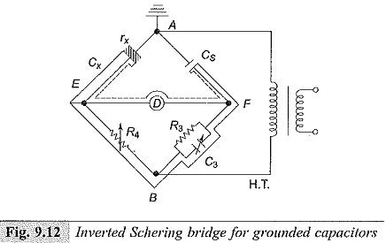
Schering Bridge Arrangement for Grounded Capacitors:
For safety reasons and to define the shield potentials with respect to each other, one of the terminals of the High Voltage Schering Bridge is earthed. This is usually the low voltage arm connection of the supply source (Terminal B of Fig. 9.11), because a low impedance arm with respect to the detector branch gives a high signal to noise ratio in measurements.
While testing grounded test objects like underground cables or bushings with flanges grounded to the tank of a transformer, one of the detector terminals (E or F) has to be grounded. In such cases, either an inverted bridge (Fig. 9.12) or a grounded detector arrangement (Fig. 9.13) has to be adopted. In the inverted bridge operation, the self-contained bridge is located inside a Faraday cage at the high voltage terminal and a standard capacitor is mounted on insulating supports. The variable arms are operated by insulated isolating rods. Sometimes, the operator himself will be inside the Faraday cage.
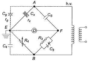
In the grounded detector arrangement, stray capacitances of the high voltage terminal (Cg) and of the source, leads, etc. come in parallel with the test object. Henge, the balancing is to be done in two steps. First, the test object is disconnected and the capacitance Cg and tan (δg) are measured. Then the test object is connected and a new balance is obtained. The second balance gives,
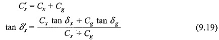
Hence, the actual capacitance and dissipation factor of the test object are
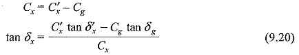
The accuracy of the measurement is poor, if the ground capacitance is large compared to the test object capacitance.