High Voltage Test on Cables:
Cables are very important electrical apparatus for transmission of electrical energy by underground means. They are also very important means for transmitting voltage signals at High Voltage Test on Cables. For power engineers, large power transmission cables are of importance, and hence testing of power cables only is considered here. Of the different electrical and other tests prescribed, the following are important to ensure that cables withstand the most severe conditions that are likely to arise in service.
Different tests on cables may be classified into
- mechanical tests like bending test, dripping and drainage test, and fire resistance and corrosion tests,
- thermal duty tests,
- dielectric power factor tests,
- power frequency withstand voltage tests,
- impulse withstand voltage tests,
- partial discharge tests, and
- life expectancy tests.
Here only the electrical tests are described, i.e. tests (iii) to (vii).
Preparation of the Cable Samples:
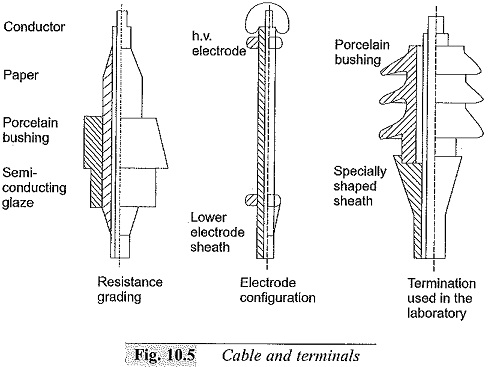
For High Voltage Test on Cables and withstand tests, samples have to be carefully prepared and terminated; otherwise, excessive leakage or end flashovers may occur during testing. The normal length of the cable sample used varies from about 50 cm to 10 m. The terminations are usually made by shielding the end conductor with stress shields or terminations to relieve the ends from excessive high electrical stresses. A few terminations are shown in Fig. 10.5. During power factor tests, the cable ends are provided with shields so that the surface leakage current is avoided from the measuring circuits.
Dielectric Power Factor Test:
The dielectric power factor test is done using the high voltage Schering bridge (see Section 9.3A). The power factor or dissipation factor tan δ is measured at 0.5, 1.0, 1.66, and 2.0 times the rated voltage (phase to ground) of the cable. The maximum value of the power factor and the difference in power factor between the rated voltage and 1.66 times the rated voltage, as well as, between the rated voltage and two times the rated voltage are specified. Sometimes, difficulty is felt in supplying the charging voltamperes of the cable from the available source. In such cases, a choke is used or a suitably rated transformer winding is used in series with the cable to form a resonant circuit. This improves the power factor and raises the test voltage between the cable core and the sheath to the required value, when a source of High Voltage Test on Cables and high capacity is used. The Schering bridge has to be given protection against overvoltages, in case breakdown occurs in the cables,
High Voltage Tests on Cables:
Cables are tested for withstand voltages using the power frequency a.c., d.c., and impulse voltage. At the time of manufacture the entire cable is passed through a high voltage test at the rated voltage to check the continuity of the cable. As a routine test, the cable is tested applying an a.c. voltage of 2.5 times the rated value for 10 min. No damage to the cable insulation should occur. Type tests are done on cable samples using both high voltage d.c. and impulse voltages. The d.c. test consists of applying 1.8 times the rated d.c. voltage of negative polarity for 30 min., and the cable system is said to be fit, if it withstands the test. For impulse tests, impulse voltage of the prescribed magnitude as per specifications is applied, and the cable has to withstand five applications without any damage. Usually, after the impulse test, the power frequency dielectric power factor test is done to ensure that no failure occurred during the impulse test.
Partial Discharges:
(a) Discharge Measurement
Partial discharge measurements and the discharge locations are important for cables, since the life of the insulation at a given voltage stress depends on the internal discharges. Also, the weakness of the insulation or faults can be detected with the help of these tests; the portion of the cable if weak may be removed, if necessary. The general arrangement for partial discharge tests is the same as described in Sec. 9.4.
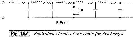
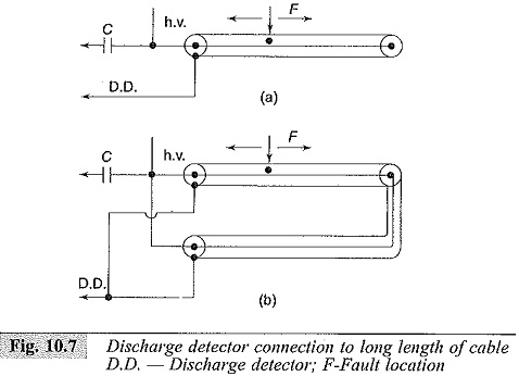
The equivalent circuit of the cable for discharges is shown in Fig. 10.6, and the cable connection to the discharge detector through the coupling condenser is shown in Figs 10.7a and b. If the detector is connected through a coupling capacitor to one end of the cable as in Fig. 10.7a, it will receive the, transient travelling wave directly from the cavity towards the nearer end, and after a short time, a second travelling wave pulse reflected from the far end is observed. Thus, the detected response is the combination of the above two transient pulses. But, if the connections are made as in Fig. 10.7b, no severe reflection is involved except as a second order effect of negligible magnitude. Now two transients will arrive at both the ends of the cable, and the superposition of the two pulses is detected. This can be obtained by adding the responses of the two transients. The superpositions of the two responses may give rise to a serious error in the measurement of the discharge magnitude. The magnitude of the possible error may be determined mainly by the shape of the response of the discharge detector.
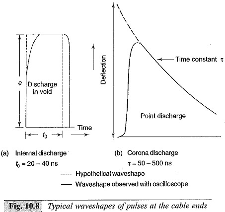
(b) Location of Discharges:
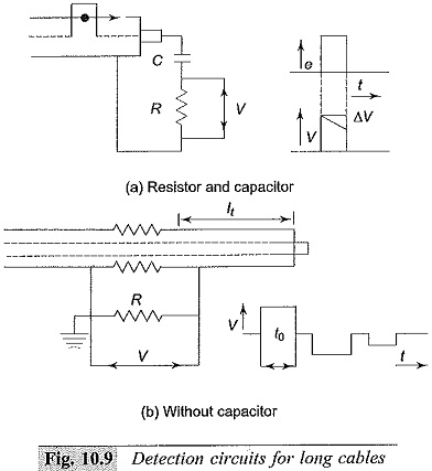
The voltage dip caused by a discharge at a fault or a void is propagated as a travelling wave along the cable. This wave is detected as a voltage pulse across the terminals of the cable ends. By measuring the time duration between the pulses, the distance at which the discharge is taking place from the cable end can be determined. The shapes of the voltage pulses depend on the nature of the discharges. Typical waveshapes are given in Fig. 10.8.
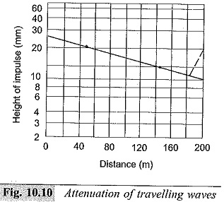
The detection circuits for the pulses are shown in Fig. 10.9, and the attenuation of the travelling wave in cables is given in Fig. 10.10. Usually, the pulses detected across the resistor are distorted after passing through the amplifier of the discharge detector.
(c) Scanning Method:
In order to scan the entire cable length for voids or imperfections in manufacture, the bare core of the cable is passed through a high electric field and the discharge location is done. The core of the material is passed through a tube of insulating material filled with distilled water. Four electrodes in the form of rings are mounted at both ends of tube as well as at the middle, such that they have electrical contact with the water. The middle electrodes are energized with a High Voltage Test on Cables, and the other two electrodes and cable conductor are grounded. If a discharge occurs in the portion between the middle electrodes, as the cable is passed between the middle electrodes portion, the discharge is detected and is located at that length of cable.
(d) Life Tests:
Life tests at e intended for reliability studies in service. In order to determine the expected life to the cable under normal stress, accelerated life tests using increased voltages are performed on actual cable lengths. It is established that the relation between the maximum electrical stress Em and the life of the cable insulation in hours t approximately follows the relationship![]()
where,
K = constant which depends on the field conditions and the material, and
n = life index depending on the material.
By conducting long duration life tests at increased stress (1 hr to about 1000 hr) the expected life at the rated stress may be determined.