Laying of Underground Cables:
The reliability of Laying of Underground Cables network depends to a considerable extent upon the proper laying and attachment of fittings i.e., cable end boxes, joints, branch connectors etc.
There are three main methods of Laying of Underground Cables viz.,
- Direct laying,
- Draw-in system and the
- Solid system.
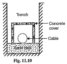
1.Direct laying: This method of Laying of Underground Cables is simple and cheap and is much favoured in modern practice. In this method, a trench of about l .5 meters deep and 45 cm wide is dug. The trench is covered with a layer of fine sand (of about 10 cm thickness) and the cable is laid over this sand bed. The sand prevents the entry of moisture from the ground and thus protects the cable from decay. After the cable has been laid in the trench, it is covered with another layer of sand of about 10 cm thickness.
The trench is then covered with bricks and other materials in order to protect the cable from mechanical injury. When more than one cable is to be laid in the same trench, a horizontal or vertical inter-axial spacing of at least 30 cm is provided in order to reduce the effect of mutual heating and also to ensure that a fault occurring on one cable does not damage the adjacent cable. Cables to be laid in this way must have serving of bituminised paper and hessian tape so as to provide protection against concision and electorlysis.
Advantages
- It is a simple and less costly method.
- It gives the best conditions for dissipating the heat generated in the cables.
- It is a clean and safe method as the cable is invisible and free from external disturbances.
Disadvantages
- The extension of load is possible only by a completely new excavation which may cost as much as the original work.
- The alterations in the cable network cannot be made easily.
- The maintenance cost is very high.
- Localisation of fault is difficult.
- It cannot be used in congested areas where excavation is expensive and inconvenient.
This method of laying cables is used in open areas where excavation can be done conveniently and at low cost.
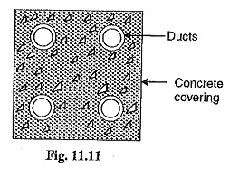
2.Draw-in system: In this method, conduit or duct of glazed stone or cast iron or concrete are laid in the ground with manholes at suitable positions along the cable route. The cables are then pulled into position from manholes. Fig. 11.11 shows section through four-way underground duct line. Three of the ducts carry transmission cables and the fourth duct carries relay protection connection, pilot wires. Care must be taken that where the duct line changes direction ; depths, dips and offsets be made with a very long radius or it will be difficult to pull a large cable between the manholes. The distance between the manholes should not be too long so as to simplify the pulling in of the cables. The cables to be laid in this way need not be armoured but must be provided with serving of hessian and jute in order to protect them when being pulled into the ducts.
Advantages
- Repairs, alterations or additions to the cable network can be made without opening the
- As the cables are not armoured, therefore, joints become simpler and maintenance cost is reduced considerably.
- There are very less chances of fault occurrence due to strong mechanical protection provided by the system.
Disadvantages
- The initial cost is very high.
- The current carrying capacity of the cables is reduced due to the close grouping of cables and unfavorable conditions for dissipation of heat.
This method of cable laying is suitable for congested areas where excavation is expensive and inconvenient, for once the conduits have been laid, repairs or alterations can be made without opening the ground. This method is generally used for short length cable routes such as in workshops, road crossings where frequent digging is costlier or impossible.
3.Solid system: In this method of laying, the cable is laid in open pipes or troughs dug out in earth along the cable mule. The troughing is of cast iron, stoneware, asphalt or treated wood. After the cable is laid in position, the troughing is filled with a bituminous or asphaltic compound and covered over. Cables laid in this manner an usually plain lead covered because troughing affords good mechanical protection.
Disadvantages
- It is more expensive than direct laid system.
- It requires skilled labour and favourable weather conditions.
- Due to poor heat dissipation facilities, the current carrying capacity of the cable is reduced.
In view of these disadvantages, this method of Laying of Underground Cables is rarely used now-adays.
Insulation Test Single Core Cable:
The cable conductor is provided with a suitable thickness of insulating material in order to prevent leakage current. The path for leakage current is radial through the insulation. The opposition offered by insulation to leakage current is known as insulation resistance of the cable. For satisfactory operation, the insulation resistance of the cable should be very high.
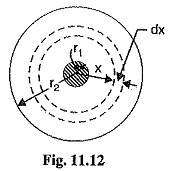
Consider a single-core cable of conductor radius r1 and internal sheath radius r2 as shown in Fig. 11.12. Let I be the length of the cable and p be the resistivity of the insulation.
Consider a very small layer of insulation of thickness dx at a radius x. The length through which leakage current tends to flow is dx and the area of X-section offered to this flow is 2π x l.
Insulation resistance of considered layer
![]()
Insulation resistance of the whole cable is
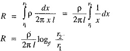
This shows that insulation resistance of a cable is inversely proportional to its length. In other words, if the cable length increases, its insulation resistance decreases and vice-versa.