Types of Strain Gauge Transducer:
Types of Strain Gauge Transducer are three types, namely
- Wire Strain Gauge
- Foil Strain Gauge
- Semiconductor Strain Gauge
Wire Strain Gauge:
Wire Strain Gauge has three types namely,
- Grid Type Strain Gauge
- Rossette Type Strain Gauge
- Torque Type Strain Gauge
- Helical Type Strain Gauge
The grid arrangement of the wire element in a bonded strain gauge creates a problem not encountered in the use of unbonded strain gauges. To be useful as a strain gauge, the wire element must measure strain along one axis. Therefore complete and accurate analysis of strain in a rigid member is impossible, unless the direction and magnitude of stress are known. The measuring axis of a strain gauge is its longitudinal axis, which is parallel to the wire element, as shown in Fig. 13.6.
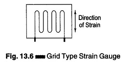
When a strain occurs in the member being measured, along the transverse axis of the gauge, it also affects the strain being measured parallel to the longitudinal axis. This introduces an error in the response of the gauge.
In most applications, some degree of strain is present along the transverse axis and the transverse sensitivity must be considered in the final gauge output. Transverse sensitivity cannot be completely eliminated, and in highly accurate measurements the resultant gauge error must be compensated for.
If the axis of the strain in a component is unknown, Strain Gauge Transducer Types may be used to determine the exact direction. The standard procedure is to place several gauges at a point on the member’s surface, with known angles between them. The magnitude of strain in each individual gauge is measured, and used in the geometrical determination of the strain in the member. Figure 13.7 shows a three-element strain gauge, called a Rossette gauge, in which the angle between any two longitudinal gauge axes is 45°.
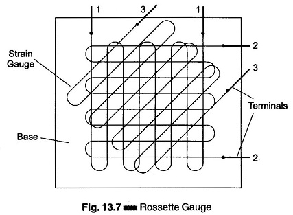
The 45° Rossette gauge is, in general, the most popular one. There are different shapes and sizes of Strain Gauge Transducer Types for various purposes.
Serving a similar, but not specialized, purpose are gauges with specially modified grid configurations, such as those shown in Figs. 13.8(a), (b) and (c).
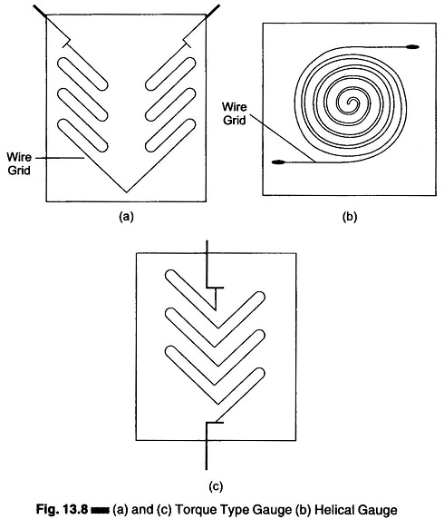
A measurement of this type would be useful at the cross-point of an X-shaped frame.
The latest in strain gauges is the etched foil strain gauge. This device uses the technique of PCB design. Its physical and electrical characteristics are superior to bonded wire strain gauges in almost every respect.
The size of strain gauges varies with application. They can be as small as 3 sq.mm. Usually they are larger, but not more than 2.5 mm long and 12.5 mm wide.
To obtain good results, it is desirable that a resistance wire strain gauge have the following characteristics.
- The Strain Gauge Transducer Types should have a high value of gauge factor (a high value of gauge factor indicates a large change in resistance for particular strain, implying high sensitivity).
- The resistance of the strain gauge should be as high as possible, since this minimises the effects of undesirable variations of resistance in the measurement circuit. Typical resistances of strain gauges are 120 Ω, 350 Ω and 1000 Ω. A high resistance value results in lower sensitivity. Hence, in order to get high sensitivity, higher bridge voltages have to be used. The bridge voltage is limited by the maximum current carrying capacity of the wires, which is typically 30 mA.
- The strain gauge should have a low resistance temperature coefficient. This is necessary to minimise errors on account of temperature variation, which affects the accuracy of measurements. (Temperature compensation is also used).
- The strain gauge should not have hysteresis effects in its response.
- In order to maintain constancy of calibration over the entire range of the strain gauge, it should have linear characteristics, i.e. the variation in resistance should be a linear function of the strain.
- Strain gauges are frequently used for dynamic measurements and hence their frequency response should be good. Linearity should be maintained within specified accuracy limits over the entire frequency range.
- Leads used must be of materials which have low and stable resistivity and low resistance temperature coefficient.
Foil Strain Gauge:
This class of strain gauges is an extension of the resistance wire strain gauge. The strain is sensed with the help of a metal foil. The metals and alloys used for the foil and wire are nichrome, constantan (Ni + Cu), isoelastic (Ni + Cr + Mo), nickel and platinum.
Foil gauges have a much greater dissipation capacity than wire wound gauges, on account of their larger surface area for the same volume. For this reason, they can be used for a higher operating temperature range. Also, the large surface area of foil gauges leads to better bonding.
Foil type Strain Gauge Transducer Types have similar characteristics to wire strain gauges. Their gauge factors are typically the same.
The advantage of foil type Strain Gauge Transducer Types is that they can be fabricated on a large scale, and in any shape. The foil can also be etched on a carrier.
Etched foil gauge construction consists of first bonding a layer of strain sensitive material to a thin sheet of paper or bakelite. The portion of the metal to be used as the wire element is covered with appropriate masking material, and an etching solution is applied to the unit. The solution removes that portion of the metal which is not masked, leaving the desired grid structure intact.
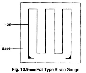
This method of construction enables etched foil strain gauges to be made thinner than comparable wire units, as shown in Fig. 13.9. This characteristics, together with a greater degree of flexibility, allows the etched foil to be mounted in more remote and restricted places and on a wide range of curved surfaces.
The longitudinal sensitivity of the foil gauge is approximately 5% greater than that of similar wire elements. The transverse strain sensitivity of this gauge is smaller 1/3 to 1/2 of similar wire gauges. The hysteresis of the foil gauge is also 1/3 to 1/2 of a wire strain gauge.
(The term hysteresis, as used in Strain Gauge Transducer Types, is defined as follows. If the resistance of a strain gauge is measured with no strain applied, and the gauge is then stressed to its maximum usable resistance value, the measured resistance, after the stress is removed, differs from the original value. The inability of the gauge element to resume the exact physical form it had before being elongated, produces the difference in resistance. This effect is called hysteresis.)
The resistance film formed is typically 0.2 mm thick. The resistance value of commercially available foil gauges is between 50 and 1000 Ω The resistance films are vacuum coated with ceramic film and deposited on a plastic backing for insulation.
Semiconductor Strain Gauge:
To have a high sensitivity, a high value of gauge factor is desirable. A high gauge factor means relatively higher change in resistance, which can be easily measured with a good degree of accuracy.
Semiconductor strain gauges are used when a very high gauge factor is required. They have a gauge factor 50 times as high as wire strain gauges. The resistance of the semiconductor changes with change in applied strain.
Semiconductor strain gauges depend for their action upon the piezo resistive effect, i.e. change in value of the resistance due to change in resistivity, unlike metallic gauges where change in resistance is mainly due to the change in dimension when strained. Semiconductor materials such as germanium and silicon are used as resistive materials.
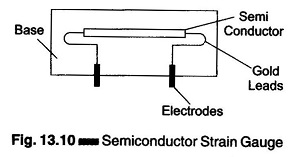
A typical strain gauge consists of a strain material and leads that are placed in a protective box, as shown in Fig. 13.10. Semiconductor wafer or filaments which have a thickness of 0.05 mm are used. They are bonded on suitable insulating substrates, such as teflon.
Gold leads are generally used for making contacts. These strain gauges can be fabricated along with an IC Op Amp which can act as a pressure sensitive transducer. The large gauge factor is accompanied by a thermal rate of change of resistance approximately 50 times higher than that for resistive gauges. Hence, a semiconductor strain gauge is as stable as the metallic type, but has a much higher output.
Simple temperature compensation methods can be applied to semiconductor strain gauges, so that small values of strain, that is micro strains, can also be measured.
The gauge factor of this type of semiconductor strain gauge is 130 ± 10% for a unit of 350 Ω, 1″ long, 1/2″ wide and 0.005″ thick. The gauge factor is determined at room temperature at a tensile strain level of 1000 micro strain (1000 micro in/in. of length). The maximum operating tensile strain is ± 3000 micro strain, with a power dissipation of 0.1 W. The semiconductor strain gauge also has low hysteresis and is susceptible to regular methods of temperature compensation. The semiconductor strain gauge has proved itself to be a stable and practical device for operation with conventional indicating and recording systems, to measure small strains from 0.1-500 micro strain.
Advantages of Semiconductor Strain Gauge:
- Semiconductor strain gauges have a high gauge factor of about + 130. This allows measurement of very small strains, of the order of 0.01 micro
- Hysteresis characteristics of semiconductor strain gauges are excellent, e. less than 0.05%.
- Life in excess of 10 x 106 operations and a frequency response of 1012 HZ.
- Semiconductor strain gauges can be very small in size, ranging in length from 0.7 to 7.0 mm.
Disadvantages of Semiconductor Strain Gauge:
- They are very sensitive to changes in temperature.
- Linearity of semiconductor strain gauges is poor.
- They are more expensive.