Strain Gauge Factor Derivation:
The Strain Gauge Factor Derivation is an example of a passive transducer that uses the variation in electrical resistance in wires to sense the strain produced by a force on the wires.
It is well known that stress (force/unit area) and strain (elongation or compression/unit length) in a member or portion of any object under pressure is directly related to the modulus of elasticity.
Since strain can be measured more easily by using variable resistance transducers, it is a common practice to measure strain instead of stress, to serve as an index of pressure. Such transducers are popularly known as strain gauges.
If a metal conductor is stretched or compressed, its resistance changes on account of the fact that both the length and diameter of the conductor changes. Also, there is a change in the value of the resistivity of the conductor when subjected to strain, a property called the piezo-resistive effect. Therefore, resistance strain gauges are also known as piezo resistive gauges.
Many detectors and transducers, e.g. load cells, torque meters, pressure gauges, temperature sensors, etc. employ Strain Gauge Factor Derivation as secondary transducers.
When a gauge is subjected to a positive stress, its length increases while its area of cross-section decreases. Since the resistance of a conductor is directly proportional to its length and inversely proportional to its area of cross-section, the resistance of the gauge increases with positive strain. The change in resistance value of a conductor under strain is more than for an increase in resistance due to its dimensional changes. This property is called the piezo-resistive effect.
The following types of Strain Gauge Factor Derivation are the most important.
- Wire Strain Gauge
- Foil Strain Gauge
- Semiconductor Strain Gauge
Resistance Wire Gauge:
Resistance wire gauges are used in two basic forms, the unbonded type, and the bonded type.
1. Unbonded Resistance Wire Strain Gauge:
An unbonded strain gauge consists of a wire streched between two points in an insulating medium, such as air. The diameter of the wire used is about 25 μm. The wires are kept under tension so that there is no sag and no free vibration. Unbonded Strain Gauge Factor Derivation Derivation are usually connected in a bridge circuit. The bridge is balanced with no load applied as shown in Fig. 13.3.
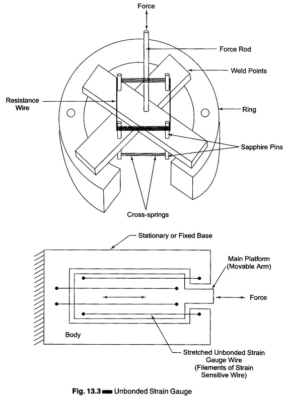
When an external load is applied, the resistance of the Strain Gauge Factor Derivation changes, causing an unbalance of the bridge circuit resulting in an output voltage. This voltage is proportional to the strain. A displacement of the order of 50μm can be detected with these strain gauges.
2. Bonded Resistance Wire Strain Gauge:
A metallic bonded Strain Gauge Derivation is shown in Fig. 13.4.
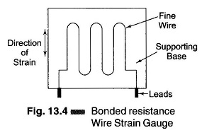
A fine wire element about 25 μm (0.025 in.) or less in diameter is looped back and forth on a carrier (base) or mounting plate, which is usually cemented to the member undergoing stress. The grid of fine wire is cemented on a carrier which may be a thin sheet of paper, bakelite, or teflon. The wire is covered on the top with a thin material, so that it is not damaged mechanically. The spreading of the wire permits uniform distribution of stress. The carrier is then bonded or cemented to the member being studied. This permits a good transfer of strain from carrier to wire.
A tensile stress tends to elongate the wire and thereby increase its length and decrease its cross-sectional area. The combined effect is an increase in resistance, as seen from the following equation
![]()
where
- ρ = the specific resistance of the material in Ωm.
- l = the length of the conductor in m
- A = the area of the conductor in m2
As a result of strain, two physical parameters are of particular interest.
- The change in gauge resistance.
- The change in length.
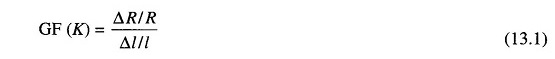
The measurement of the sensitivity of a material to strain is called the gauge factor (GF). It is the ratio of the change in resistance ΔR/R to the change in the length Δl/l
where
- K = gauge factor
- ΔR = the change in the initial resistance in Ω’s
- R = the initial resistance in Ω (without strain)
- Δ l = the change in the length in m
- l = the initial length in m (without strain)
Since strain is defined as the change in length divided by the original length,
i.e.

Eq. (13.1) can be written as

where σ is the strain in the lateral direction.
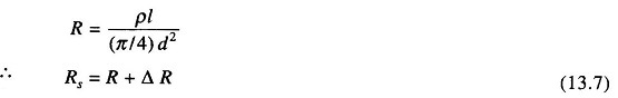
The resistance of a conductor of uniform cross-section is
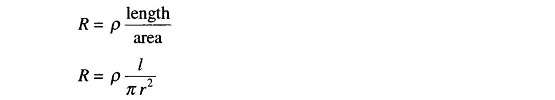
Since
where
- ρ= specific resistance of the conductor
- l = length of conductor
- d= diameter of conductor
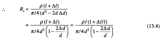
When the conductor is stressed, due to the strain, the length of the conductor increases by Δl and the simultaneously decreases by Δd in its diameter. Hence the resistance of the conductor can now be written as

Since Δd is small, Δd2 can be neglected
Now, Poisson’s ratio μ is defined as the ratio of strain in the lateral direction to strain in the axial direction, that is,
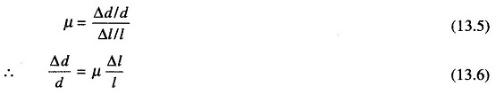
Substituting for Δd/d from Eq. (13.6) in Eq. (13.4), we have

Rationalizing, we get
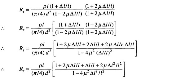
Since Δl is small, we can neglect higher powers of Δl.
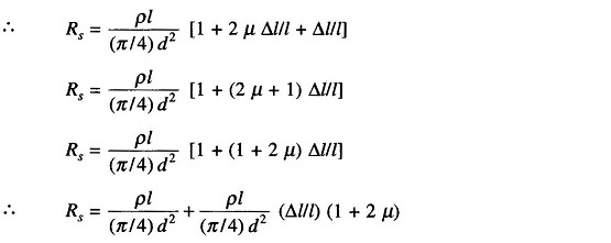
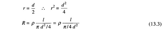
Since from Eq. (13.3),
where

The gauge factor will now be