Measurement of Capacitance using Schering Bridge:
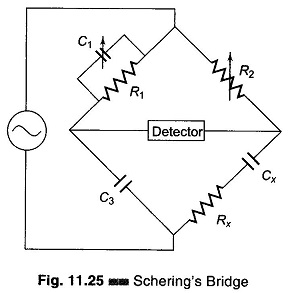
A very important bridge used for the precision measurement of capacitors and their insulating properties is the Schering Bridge Experiment. Schering Bridge basic circuit arrangement is given in Fig. 11.25. The standard capacitor C3 is a high quality mica capacitor (low-loss) for general measurements, or an air capacitor (having a very stable value and a very small electric field) for insulation measurement.
For balance, the general equation is

where
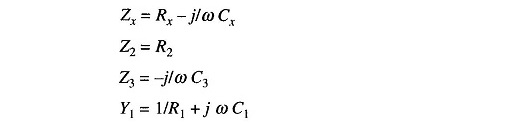
as
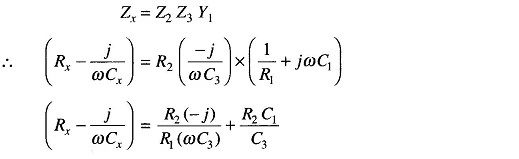
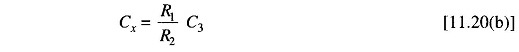
Equating the real and imaginary terms, we get
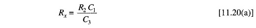
and
The dial of capacitor C1 can be calibrated directly to give the dissipation factor at a particular frequency.
The dissipation factor D of a series RC circuit is defined as the contangent of the phase angle.

Also, D is the reciprocal of the quality factor Q, i.e. D = 1/Q. D indicates the quality of the capacitor.
Commercial units measure from 100 pf – 1 μf with ± 2% accuracy. The dial of C3 is graduated in terms of direct readings for Cx, if the resistance ratio is maintained at a fixed value.
This Schering Bridge is widely used for testing small capacitors at low voltages with very high precision.
The lower junction of the bridge is grounded. At the frequency normally used on this bridge, the reactances of capacitor C3 and Cx are much higher than the resistances of R1 and R2. Hence, most of the voltage drops across C3 and Cx and very little across R1 and R2. Hence if the junction of R1 and R2 is grounded, the detector is effectively at ground potential. This reduces any stray-capacitance effect, and makes the bridge more stable.