Stepper Motor Classification:
The Stepper Motor Classification based on the construction and principle of operation. These are
- Variable reluctance motors
- Permanent magnet motors
- Hybrid stepping motors
- Claw pole motors with permanent magnets
The stepper motors are used for linear motors also. These are also classified as ‘variable reluctance motors’ and ‘permanent magnet motors’.
Variable Reluctance Motors
The principle of operation of variable reluctance motors is based on the property of the flux lines tending to occupy low reluctive path. The stator and rotor therefore get aligned such that the magnetic reluctance is minimum. This type of motors being basic type, have a stator with different sets of winding which are excited by dc alternately. Each set may be called a phase. A simple motor may have six teeth on the stator. On each of the teeth there is a winding. The windings on the diametrically opposite teeth are connected in series and the resulting one is called the phase of the motor. Thus a motor with 6 slots will have three phases. The rotor on the other hand is simply made of magnetic material. It also has a slotted structure but no winding. This is capable of movement inside the stator whenever a phase of the stator is excited. Both the stator and rotor are made up of high quality magnetic materials having very high permeability so that the exciting current required is extremely small. A three phase variable reluctance stepping motor with four rotor slots is shown in Fig. 8.25. The principle of operation of the motor is explained with reference to Fig. 8.25.
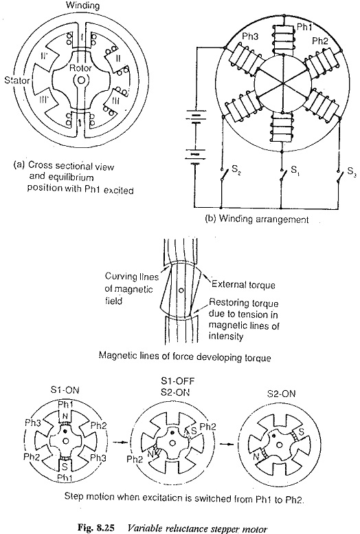
The coils on the teeth AA′ are excited by the dc voltage by closing the switches S1. The stator and rotor constitute the magnetic circuit and a magnetic flux is set up. The nature of the flux lines being to occupy the path of least reluctance tries to move the rotor to align with the stator as shown in Fig. 8.25. The rotor stops at a position where the reluctance is minimum and this position is said to be the equilibrium position. The next equilibrium position is obtained by exciting the next phase. The angle between two successive equilibrium positions is known as the step angle. The rotor moves by one step when a winding is excited. If any displacement is likely to occur in the rotor due to application of load or any disturbing forces, the rotor has a tendency to be in the equilibrium position. To accomplish this a torque is developed which is called the restoring torque in Fig.(8.25). This restoring torque is due to the property of the flux lines to align the stator and rotor such that they have the least reluctive path.
Any switching operation to change the position is accompained by an increase in the reluctance which brings in a torque (or force) to seek the alignment of the rotor and stator, and the rotor is in equilibrium in the new position. Thus the rotor moves by one step or step angle at every new excitation. In the present example when S2 is closed, opening S1 the rotor moves by 30° in the acw direction. 30° is step angle in this case. The rotor will come to its original position after completion one rotor tooth pitch rotation which may take 3 steps. These are detailed in Fig. 8.25.
The accuracy of positioning which is a desired quality of a Stepper Motor Classification requires a high torque from a given volume of rotor (which is normally small). To get the high torque capability a small air gap may be required. A small air gap means low reluctance and high flux providing a good torque. The restoring torque developed is also sufficiently high so that the displacement from an equilibrium position is rather small.
The resolution of Stepper Motor Classification will be very high if the step angle is smaller. This can be made smaller by increasing the number of stator and rotor teeth. This depends actually on the stator phases and how the stator teeth are divided into phases. For example 12 teeth in the stator can be divided as 3 phases, or 6 phases. If rotor teeth are 8 in the former case the step angle is 15° and in the latter it is 7.5°. The step angle is therefore given by
![]()
where
m is the number of phases
Nr is rotor teeth.
To reduce the step angle the rotor teeth must be increased. The stator teeth is not a direct factor in determining the step angle or step number. A four phase motor with 50 rotor teeth has 200 steps/revolution or a step angle of 1.8°.
The rotor must be made to have low inertia, so that its torque/inertia ratio is higher for quick response of the motor.
Permanent magnet stepper motors
The rotor is made of a permanent magnet in permanent magnet motors. The stator is similar to that of variable reluctance motor. The coils on the stator teeth form the phases of the motor. The permanent magnet is cylindrical and housed in the multiphase stator. A four phase machine with cylindrical permanent magnet motor is shown in Fig. 8.26. The stator has four teeth around which coils are wound. The phases are excited by dc voltages using the switches. The excitation of phases in the sequence 1 2 3 4 moves the rotor in the clockwise direction. The step angle in the present case in 90°. To increase the step angle the number of stator phases and number of rotor poles must be increased. This method has limitations.
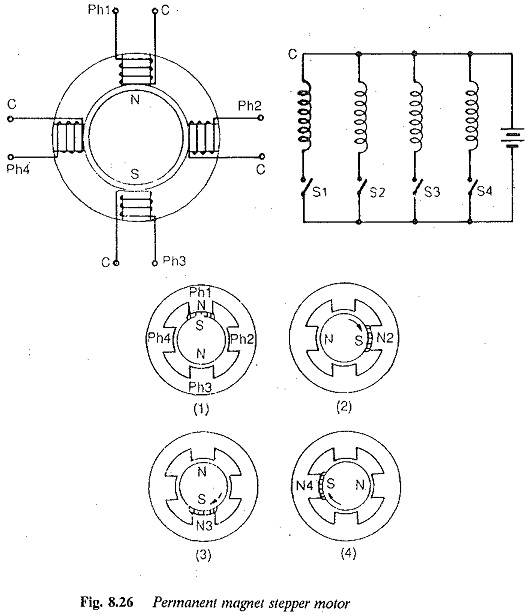
The rotor comes to rest at a fixed position even if excitation of stator ceases. The mechanism by which the rotor comes to rest is known as detent mechanism and the predetermined position is called the detent position. This is defined as the position at which a permanent magnet motor comes to lest at no load without excitation.
A permanent magnet motor has the following disadvantages:
- The motor is costly due to permanent magnets.
- The level of the magnetic remanance fixes the maximum flux density level. This being very low the torque capability of the motor is not high.
Hybrid stepping motors
One main limitation of the permanent magnet motor is the step angle. It cannot be reduced because of the limitations on the phases of the stator. To increase the step rate and have a small step angle a hybrid motor working on the principles of variable reluctance motor and permanent magnet motor. The construction of stator of a hybrid motor is almost similar to that of a variable reluctance motor (Fig. 8.27). However there is a difference in placing the windings of the stator poles. In a hybrid motor two coils of different phases are wound on the same pole whereas in a variable reluctance motor only one coil of a phase is placed on a pole. In a hybrid motor the excitation of the coils cause different magnetic polarities.
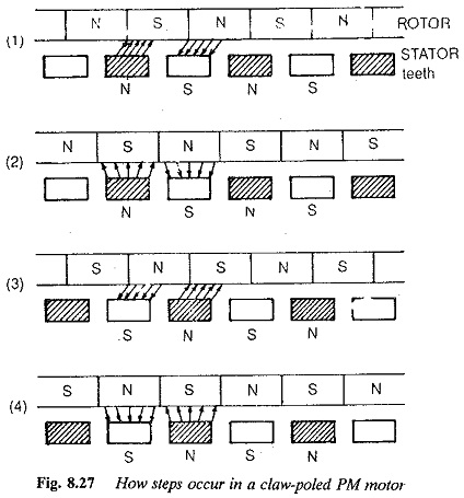
The rotor of a hybrid motor also has a different structure. The cylindrical rotor structure is magnetised to produce unipolar field. Each pole is covered by toothed soft steel. There is a misalignment between the teeth of two sections by half a tooth pitch. In some motors the stator core has misalignment. The toothed sections are made of silicon steel laminations. The stator coils generate heteropolar field.
The toothed structures of the stator and the rotor are designed to reduce the step angle in a hybrid motor. The permanent magnet is significant in producing a driving force. The torque is developed by the interaction of the two types of magnetic fields in the toothed structures in the air gap. Sequential switching on and off of the stator phases will result in the rotor motion in steps. The torque production and movement of the rotor is due to the superposition of the fields of stator phases and permanent rotor magnet. The superposition is such that the flux is strengthened on one side and weakened on the other side causing the motion of the motor. The rotor moves until the driving force is zero. At this point it has its equilibrium position. Multistack motors are used to raise the torque.
Claw pole motor with permanent magnets
A claw pole motor is also a permanent magnet stepper motor. It has the advantage of low manufacturing costs and has applications as the paper feed prime mover and head drive motor in floppy disc drives.