Stepper Motor Interface:
A stepper motor is a digital motor. It can be driven by digital signal. Fig. 15.18 shows the typical 2 phase Stepper Motor Interface using 8255. Motor shown in the circuit has two phases, with center-tap winding. The center taps of these windings are connected to the 12V supply. Due to this, motor can be excited by grounding four terminals of the two windings. Motor can be rotated in steps by giving proper excitation sequence to these windings. The lower nibble of port A of the 8255 is used to generate excitation signals in the proper sequence.
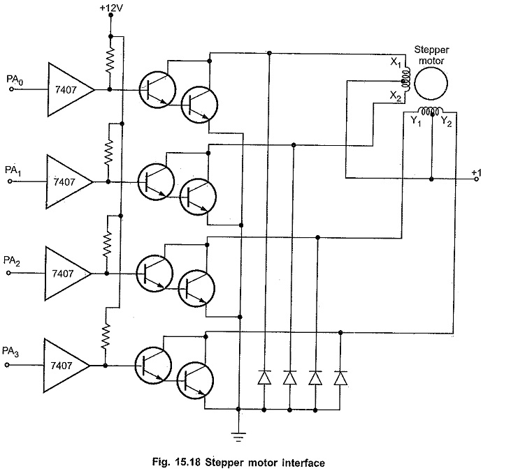
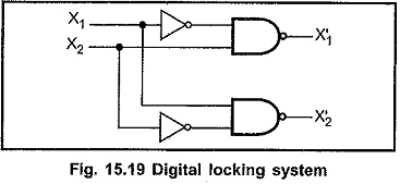
The table 15.3 shows typical excitation sequence. The given excitation sequence rotates the motor in clockwise direction. To rotate motor in anticlockwise direction we have to excite motor in a reverse sequence. The excitation sequence for Stepper Motor Interface many change due to change in winding connections. However, it is not desirable to excite both the ends of the same winding simultaneously. This cancels the flux and motor winding may damage. To avoid this, digital locking system must be designed. Fig. 15.19 (c) shows a simple digital locking system. Only one output is activated (made low) when properly excited; otherwise output is disabled (made high).
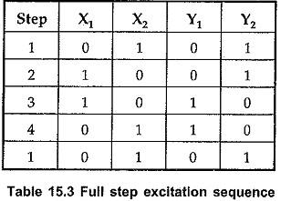
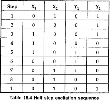
The excitation sequence given in Table 15.3 is called full step sequence. In which excitation ends of the phase are changed in one step. The excitation sequence given in table 15.4 takes two steps to change the excitation ends of the phase. Such a sequence is called half step sequence and in each step the motor is rotated by 0.9°.
We know that Stepper Motor Interface is stepped from one position to the next by changing the currents through the fields in the motor. The winding inductance opposes the change in current and this puts limit on the stepping rate. For higher stepping rates and more torque, it is necessary to use a higher voltage source and current limiting resistors as shown in Fig. 15.20.
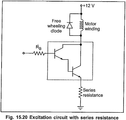
By adding series resistance, we decrease L/R time constant, which allows the current to change more rapidly in the windings. There is a power loss across series resistor, but designer has to compromise between power and speed.