RS 232 Interface Modem:
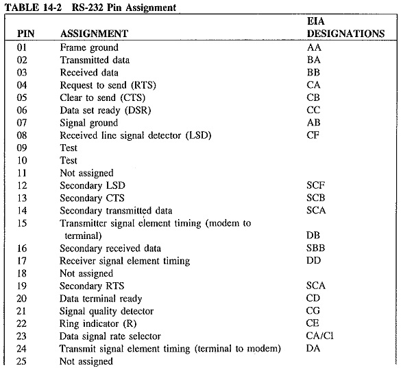
In the United States, a standard interconnection between business machine and modem is supplied by the RS 232 Interface Modem. RS 232 Interface Modem has been defined by the Electronic Industries Association (EIA) to ensure compatibility between data sets and terminal equipment. The interface uses a 25-pin Cannon or Cinch plug, where each of the 25 pins has been given a specific function by EIA, as shown in Table 14-2. The United States military data communications system uses a similar interface designated as MIL-188C, and an international interface similar to the RS-232 is also available.
The RS-232 interface specifications limit the interconnecting cable to a length of 50 ft (15 m) or, if this length is exceeded, the load capacitance at the interface point must not be greater than 2500 pF. This limitation insures that signals will operate at appropriate standards of quality.
The interface also specifies the voltage levels with which data and control signals are exchanged between data sets and business machines. Each pin in the 25-pin connector will carry either a binary 0 or a 1 to indicate activation or deactivation of control functions or data values. A binary 1 is used for making and signifies OFF, while the 0 is used for spacing and signifies ON.
The RS-232 interface can accommodate several different types of data circuit operation, using different combinations of circuit lines. For example, point-to-point dedicated system will require a minimum number of control lines in the interface, while for circuits which operate in a half-duplex mode, line-turnaround must be provided since the same pair of wires is used for both send and receive. Control circuits which will accomplish these functions are included in the RS-232 interface. In the case of another type of operation, systems which involve several remote terminals connected to a data circuit follow particular sequences of operation. The terminal wishing to send data will signal with a request-to-send (circuit CA, designated in Table 14-2, will change state), and the data set responds to the request-to-send by conducting procedures which will inform the receive station modem of the request-to-send and will conduct such tests and system set-up sequences as may be required. When the start-up procedures are completed, the receive modem will send a clear-to-send to the transmit modem, whereupon the transmit modem will cause circuit BA to change states, and transmission of data will begin. Data will be sent as alternating binary states of circuit BA, and thus data will be transferred in a serial mode. At the receive station, circuit BB will reflect the binary status of the data and will be interpreted by the business machine for processing.
Other Interfaces:
Several new interface standards have also been developed. Listed as RS-422, RS-423 and RS-449, these interfaces expand the flexibility of the RS-232. Two connectors replace the 25-pin connector of RS-232 with a 37-pin connector providing all interchange circuits except secondary channel circuits, which are provided by a separate 9-pin connector. The new standards extend the 15-m (50-ft) range of RS-232 to 60 m (200 ft). The maximum signaling rate increases under the new standards from the 20,000 bps of RS-232 to 2.048 Mbps. Ten additional exchange circuits not included under RS-232C are provided in RS-449, while three circuits provided by RS-232 have been deleted. Balanced and unbalanced circuits have been provided by the new standards, and integrated circuit technology has been considered in the definition of the electrical characteristics of the interface. The new standards have been devised to facilitate interconnection with RS-232 equipment with minimal modification.