Comparators in Power System Articles:
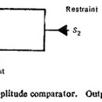
Static Amplitude Comparator: If the two input signals are S1 and S2 the amplitude comparator gives positive (yes) output only if S2/S1 ≤ K (Fig. (11.1)), S1 is the operating quantity and S2 is the restraining quantity. Ideally, the comparison of the … (Read More)
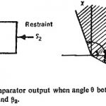
Phase Comparator Circuit: Phase Comparator Circuit technique is the most widely used for all practical directional, distance, differential and carrier relays. If the two input signals are S1 and S2 the output occurs when the inputs have a phase relationship lying … (Read More)
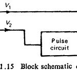
Coincidence Type Phase Comparator: The basic concept of phase comparison is simpler in that it is possible to deal with signals of equal strength whose coincidence (or noncoinecidence) is readily measurable. Considering two sinusoidal signals S1 and S2, the period of … (Read More)