Characteristics of Protective Relay:
Characteristics of Protective Relay elements using different operating principles. These principles and design criteria determine how well the basic function is performed and how in practice it deviates from the ideal. Static relays can achieve such a high performance that the departures from the ideal in practice are negligible. This high performance combined with the design flexibility makes it possible to satisfy a wide variety of requirements with a limited number of functional units. The basic elements needed to cover such a wide range of functions
Summation:
The combination of a number of electrical quantities into a single quantity through static equipment like summation transformers and sequence networks is already well known. These fit into the concept of static relaying. Summing units can be reduced in size by using new components and techniques, including active elements. Semiconductor circuits are well suited to the use of summing junctions (used in the analogue computation field) and can be applied into Characteristics of Protective Relay.
Single Input Devices:
These form the basis of many protective and control schemes as in the following:
1.Non-critical repeat function (all-or-nothing relays)—This usually produces a switching power gain of the order of 103, with a multiplicity of segregated outputs—these may be in the form of These devices are generally instantaneous with operating speeds of the order of 20 ms. or less. They may also have an associated time-delay function. Since these devices are either unenergized or energized very much in excess of marginal conditions they ensure fast response and good contact pressure in the case of electromechanical devices: Examples of this type are : attracted armature relays (telephone type), reed relays (with high speeds of the order of 1-2 ms are now available), semiconductors (specially thyristors). Repeat functions are usually
initiated by outputs from critical or measuring elements [Fig. 1.10 (a)].

2.Critical or measuring function—This requires a response to an input when the latter exceeds a prescribed critical level. Switching gain may be included but is not essential since repeat devices can he provided. Practical requirements are fast response, accuracy of setting and high reset ratio. This function is used in many protection systems such as over current, under voltage, over-voltage, differential systems etc. The elements used for these functions may be attracted armature, induction or moving coil This function can also be derived through semiconductor circuits driving electromagnetic relays like polarized moving coil or attracted armature types or reed relays or thyristors [Fig. 1.10 (b)].
3.Fixed time or definite time function—This necessitates a delay between input and output (between the application of an input and the occurrence of an output or between the removal of an input and the resetting of the output). The input is to be only non-critical (either nothing or greatly in excess of the critical sections can be combined in the inputs circuit. Practical requirements from these devices are accuracy of time setting and repeatability under successive applications [Fig. 1.10 (c)].
4.Function time-dependent on input
Two Input Devices:
With two inputs, it is possible to obtain a wide range of Characteristics of Protective Relay using different operating principles. The function is generally defined by the relationship between the inputs, which governs the boundary condition of operation. The two basic forms are as follows:
1.Amplitude comparison—One input is a restraining quantity and the other is an operating quantity so that an output is obtained when the Patio of these quantities is less than a critical value. Ideally the comparison of the amplitudes of the two inputs is independent of the level and phase relationship, of the inputs. The function is represented by a circle in the complex plane with its centre at the origin—defining the boundary of marginal operation. Examples of this are biased relays and impedance type distance relays [Fig, 1.1 (a)].
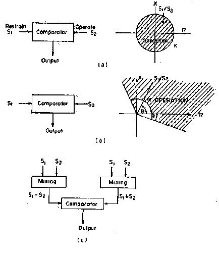
2.Phase comparison—Output appears when the inputs have a phase relationship lying within specified limits. Both inputs must exist for an output to occur—ideally the output is independent of their magnitudes, but dependent only on their phase relationship. The function as defined by the boundary of marginal operation is represented by two straight lines from the origin of the complex plane. Examples of these are directional relays, distance relays excluding the impedance type and other phase comparison relays (Fig. 1.11 (b)].
It will also be shown that either comparator becomes equivalent to the other if it is fed through the appropriate mixing units giving the sum and difference of the original inputs. Thus any Characteristics of Protective Relay can be obtained by using the amplitude or the phase comparison principle, although practical considerations might dictate preference for one scheme out of the two.
Multi-input Devices:
With more than two inputs, the range of complex characteristics is extended. Using amplitude comparison, the remaining conic section curves like ellipse, parabola, hyperbola, etc. can be obtained.
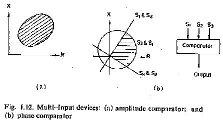
Using phase comparison, Characteristics of Protective Relay are obtained which contain discontinuities as the effective zone is the common area given by a number of straight lines and/or circular characteristics.
Equivalence of phase and amplitude comparators does not apply to multi-input case.